Video Routers
Overview
Integrating the RCP with a video router provides:
- Bi-directional synchronization between the camera selected on the RCP and the source shown on the operator’s monitor. When the operator changes camera on the RCP, the router output follows; if the source is changed on the router panel, the RCP selection updates accordingly.
- Joystick override mode, allowing the operator to see the camera while holding the preview button or joystick down, then return to the fallback signal when the override is released.
- Sharing the router configuration with other RCPs so multiple RCPs can work together while using a single connection to the router.
- The ability to generate tally status based on the source camera feeding a given router output.
Supported devices
- Pro-Bel/Snell SW-P-08 (VSM, Cerebrum, Hi, Ross switchers, etc.)
- Evertz Quartz
- AJA Kumo
- Blackmagic Videohub and ATEM
- Newtek Tricaster
- VMix
- AVMatrix Multiviewer
Configuration
Only one router should be configured per device. The UI will let you add more than one, but the behavior will be unpredictable.
All router and switcher integrations work over IP, so the RCP must be on the same network as the router.
- Open the
Configurationtab and go to theComponentssection. - Click on
+, then selectRouter / Switcher. - In the list, choose the router / switcher type that matches your device.
A new block will appear. Click on it to display the settings on the right side:
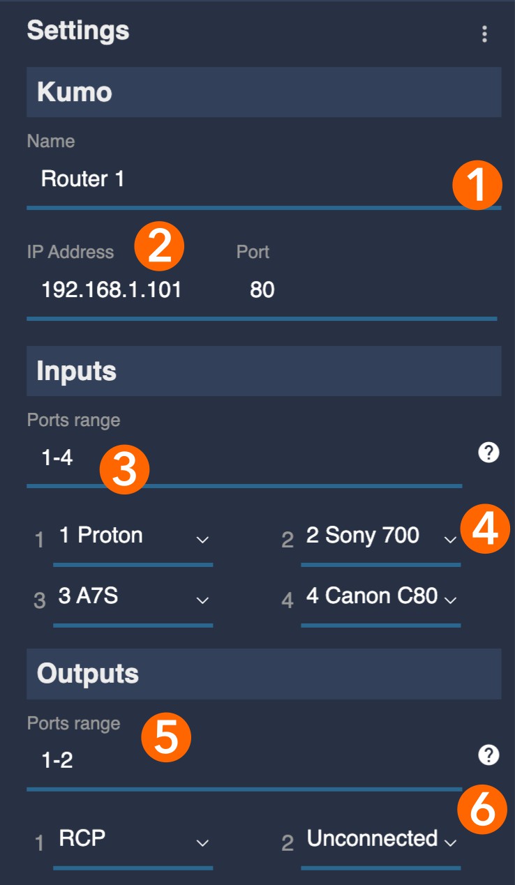
- [1] Optionally rename the router.
- [2] Enter the IP address of the router.
- [3] Select the range of inputs that will be assigned to cameras (for example:
1,2,3,1-3or1,2,5-9). - [4] Map each camera to the corresponding router inputs.
- [5] Select the range of outputs you want to consider for the monitoring.
- [6] Associate the RCP with one or more auxiliary outputs used as operators’ monitors.
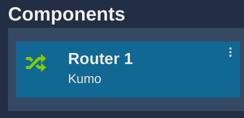
If everything is configured correctly, the router block turns green, confirming that communication is working:
Input / output fields accept lists to help filter only the relevant ports on large grids.
You can use:
- Numbers:
1,2,4(for ports 1, 2 and 4) - Ranges:
1-4,9-10(for ports 1, 2, 3, 4 and 9, 10) - Combinations:
1-3,5(for ports 1, 2, 3 and 5)
A single value such as 1 is also valid.
Joystick override configuration
This configuration uses the development interface. The main UI will be overhauled in the future, which is why this functionality is not yet available there.
Joystick Override means switching the router input to the selected camera while the preview button is pressed and held, and restoring the previous router input when the button is released.
In this mode, when no preview button is pressed, the router returns to a dedicated fallback signal. The configuration requires a few steps:
- Configure the RCP to generate level-type signals so button release is detected.
- Configure a fallback input on the router.
- Configure the RCP panel behavior, deciding whether it should follow the router or avoid generating preview actions when switching cameras.
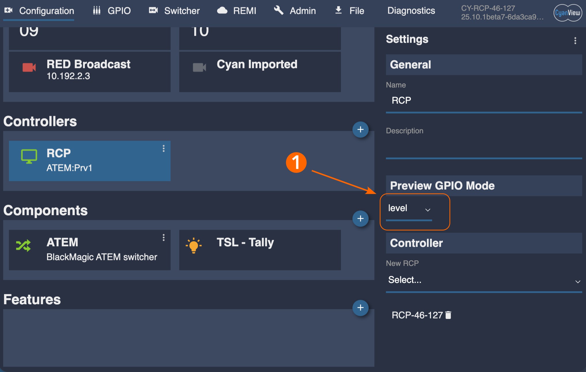
- Configure the RCP to generate level signals.
- [1] Select the "RCP" block in the configuration tab. Change the "Preview GPIO mode" in the properties on the right to "Level".
- Configure a fallback signal on the router. This is done in the development interface available by appending
/dev/app.htmlto the IP address of the RCP:http://10.192.xx.yy/dev/app.html.
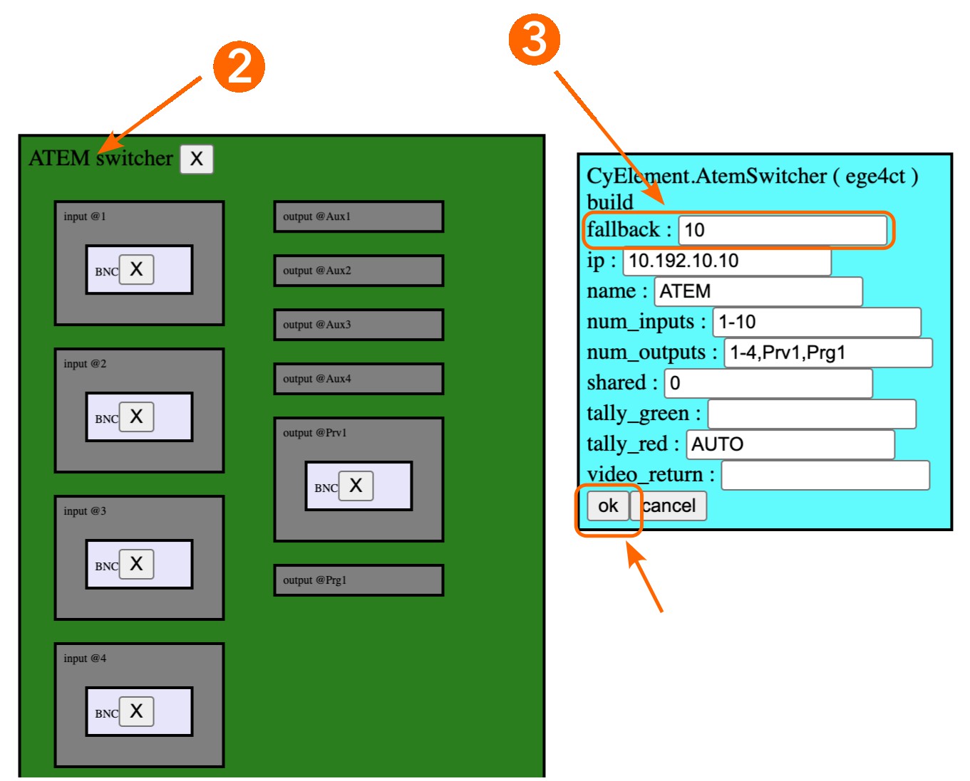
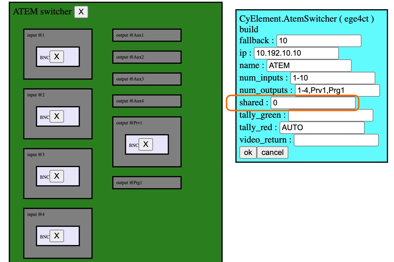
Look for the router block in the third column:
- [2] Select the router block by clicking on the outside shape (green area)
- [3] Look at the properties on the top right of the window, add the router input used for the fallback signal (in this case
10), then click on "ok".
At this point, the router should switch to the fallback input whenever the preview button of the RCP is released.
You can configure the RCP panel itself to behave in different ways:
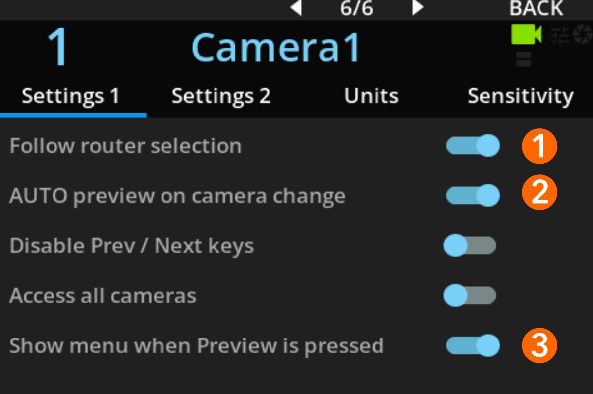
- [1] Disabling the "Follow router selection" option will make the RCP ignore the router input and always stay on the current camera. This is usually needed when multiple RCPs are used, but also if you prefer to manually select the camera on the RCP independently of the monitoring signal.
- [2] Disabling the "Auto preview on camera change" option will avoid generating "preview" actions when the camera is changed on the RCP, so the router will not be switched while changing cameras on the RCP. This is often necessary, as switching cameras would otherwise briefly switch to the selected camera before immediately falling back to the dedicated fallback signal.
- [3] "Show menu when Preview is pressed" should be disabled. This option is meant to hold the button to show the selection menu, but in this workflow the goal is to adjust parameters of the RCP; enabling it would prevent that.
Sharing a router configuration with other RCPs or devices
This configuration uses the development interface. The main UI will be overhauled in the future, which is why this functionality is not yet available there.
In many systems, especially when one RCP is used per camera, it is important to avoid creating too many connections to the router or router control system. To address this, you can configure a single RCP with the router integration and share that configuration with other RCPs.
When sharing is enabled, the other RCPs will automatically see the router in their configuration. Each RCP can then be set up as if it had its own router integration, but all of them actually use the same underlying router connection from the RCP that is sharing it.
Sharing is enabled only on the main RCP. All other RCPs will automatically see the shared router and do not need any additional configuration. To enable sharing, go to the development interface by appending /dev/app.html to the RCP IP address: http://10.192.xx.yy/dev/app.html.
Look for the router block in the third column:
- Select the router block by clicking on the outside shape (green area)
- Look at the properties on the top right of the window, set the "Shared" option from 0 to 1, then click on "ok".
Because one RCP acts as a proxy for all the others, it must remain connected for them to work. If this RCP is disconnected, even temporarily, all the other RCPs will lose their communication with the router.
At this point, the other RCPs should show the same router block in the "Components" section of their "Configuration" tab. Each RCP can then be configured with the cameras it controls as inputs and with the output used for monitoring.
Tally
In some setups, you may want to derive tally directly from router outputs. This is done by monitoring one or more router outputs and using them as the source for tally. You can also combine several outputs into a single tally signal so that a camera is considered on-air whenever any of those outputs carry that camera.
This approach is common with larger ATEM switchers that provide multiple M/Es. ATEM only exposes native tally for the first M/E; using router-based tally lets you base tally on another M/E, or even merge tally information from several M/Es.
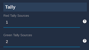
In the red and green tally fields, enter the router outputs used for program (red) and preview (green).
Each field accepts one or more router outputs:
1– a single output.1,2,3– a list of outputs, useful when you run multiple productions in parallel. Tally states from all listed outputs are combined to compute the final tally status sent to the cameras.
For ATEM, M/E program outputs use specific names such as Prg2, Prg3, etc. Refer to the ATEM integration for the exact labels.