RCP Installation
Mounting RCP
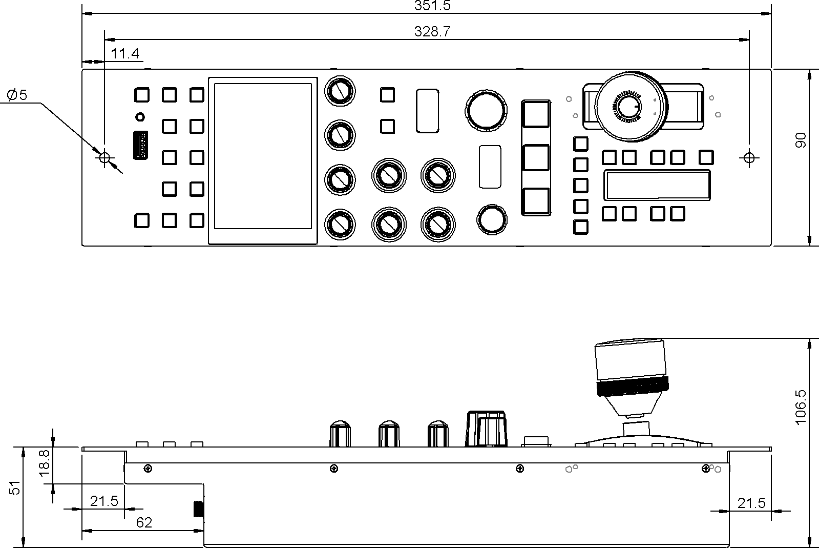
RCP-J Dimensions
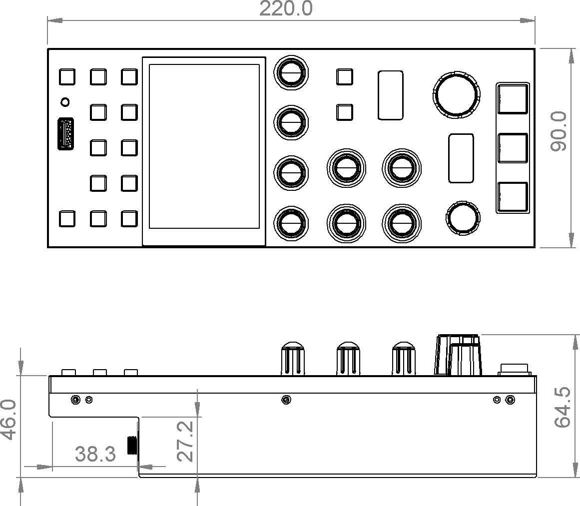
RCP dimensions
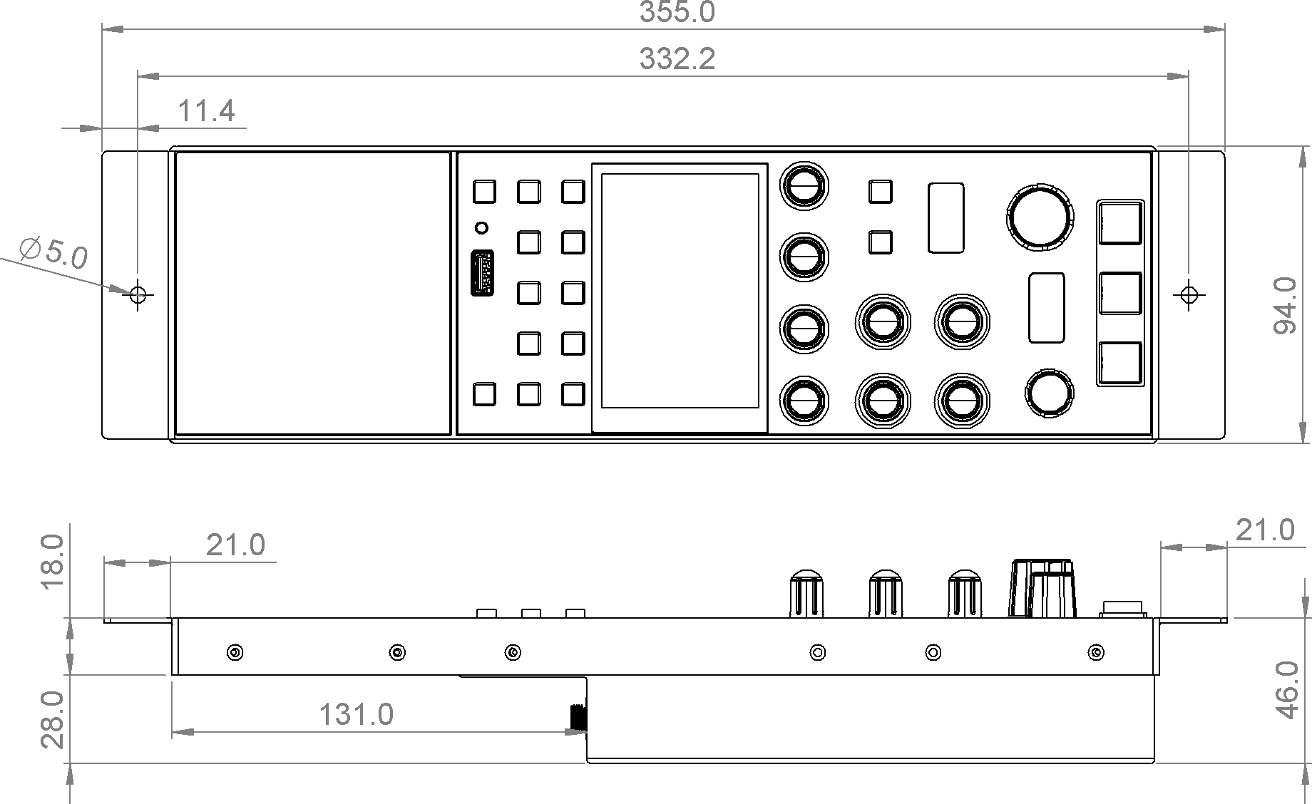
Mounting Frame for the short RCP version
To fit with standard RCP dimensions, a Mounting Frame can be added and is composed of a frame and cover.
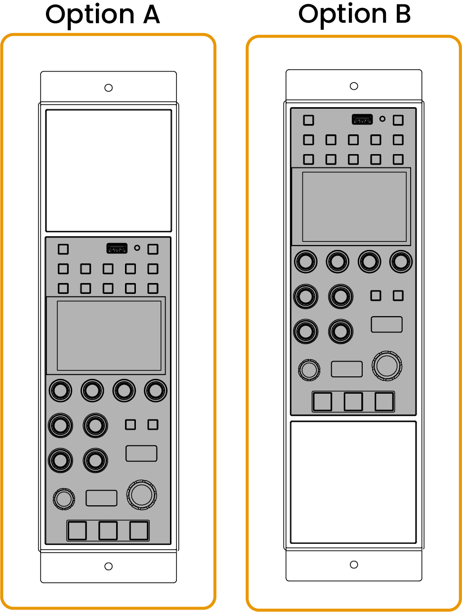
The RCP can be aligned at the bottom of the frame (option A) or at the top (option B).
Powering the RCP
The RCP can be powered from PoE or using an external 12V power supply.
-
PoE 802.3af
-
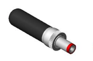
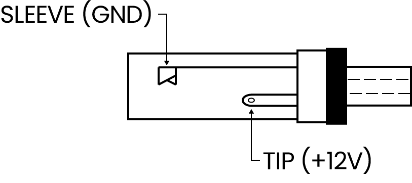
DC Input: +12V 200mA (acceptable range: 9V to 24V)
Power plug is a switchcraft 762K or compatible (5.5x2.1mm).
Networking the RCP
The RCP Ethernet port is 10/100 Mbit/s (Fast Ethernet) and can be used to control the RCP and power it when connected to a PoE (802.3af) switch/injector over the RJ45 cable.
If the RCP does not link up when connected to a switch or a media converter, verify that the network equipment supports 10/100 Mbit/s (some devices only support 1 Gbit/s, for example some switches and more often some media converters, and will not establish a link with a 10/100 port).
RCP UI
RCP is configured and managed via a Configuration Web UI.
RCP Update
Make sure your RCP runs our latest releases.
Please refer to the update manual.
Troubleshooting
RCP not detected on the network
-
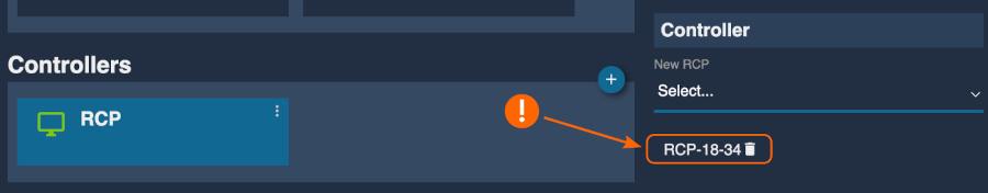
If the touchscreen stays on the Connecting... screen, this might indicate a configuration issue rather than a network issue. A typical reason is the RCP being removed from the RCP block in the Controllers section: see Configuration Web UI: Controllers. Add it back (or reset the RCP configuration to restore the default controller entries).
-
If, after booting, the touchscreen displays the camera list and live values, the internal networking is working using the factory
10.192.0.0/16network (the panel is communicating with the main camera control application). In this case, you should be able to ping the RCP factory IP (10.192.X.Y, derived from the serial number) from a computer configured with a static IP in the same range. See IP Primer.If you cannot ping the RCP in this scenario, it likely means the Ethernet interface to the internal switch is damaged: contact the support team for an RMA (see RMA procedure).
As a temporary workaround, you can plug a USB-Ethernet dongle into the RCP. It will be configured as DHCP by default, so on a DHCP-enabled network you can find its IP address in your DHCP server leases and use it to access the RCP (see USB dongles).
Force upgrade
- Unplug power (remove RJ45 if PoE, 12V if external power supply)
- Push the "lock" / "power" button (top left) and keep pressed
- Plug back the power and wait until a "loading screen" is displayed, then you can release
- Wait a couple of minutes and it should "load" the upgrade and then reboot and reload the camera list and values
Test mode (hardware check)
Use this procedure to start the internal test mode and verify each physical button and encoder:
- Press the LOCK button to go to the POWER menu (or MENU → SYSTEM → POWER).
- Press the SCREEN OFF button. The panel switches off, and only the LOCK button remains lit.
- Press and hold the MENU button while pressing the LOCK button. The hardware check menu opens.
In this menu, you can test all encoders, buttons, the touchscreen, etc.
To exit the menu, press the LOCK button and release it after the beep stops.