Overview
LanSee propose a range of devices to transport video and IP over fiber.
In this documentation, we show the integration of the SMPTE module with:
- B4 Canon lens
- a camera (here a DC SSM500)
- Cyanview CI0 to control the camera and the lend
- RCP to shade the camera (+ lens control)
And this setup will show the integration with the router/switcher and Cyanview ecosystem:
- Lansee ingest multiple video signal inputs
- the cameraman push buttons on the lens
- Cyanview RCP will switch the video signals directly inside LanSee
Wiring
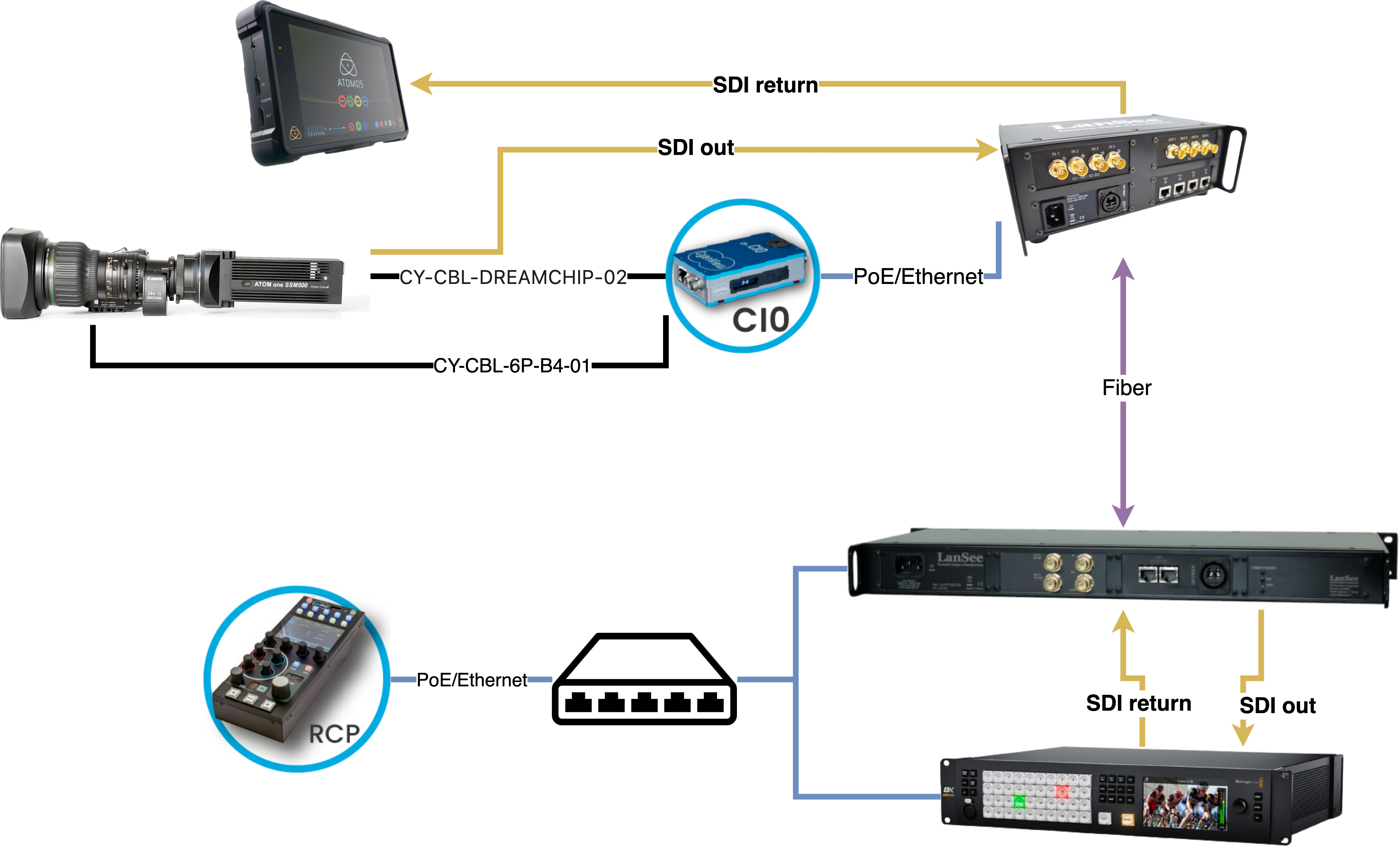
Camera side
- CI0 is powered by PoE directly from LanSee, powering/controling the lens and camera
- Dreamchip SSM500 depending on the mode will outputs:
- 2 x SDI : in trigger mode (replay is done internally on SSD), one live, one replay
- 4 x SDI : in SSM mode (EVS), 4 x phases for replay
- LanSee will ingest all SDI and give one SDI out for the monitor
CCU side
- LanSee:
- 1 x SDI input from switcher/router (program, preview, etc.)
- 2 x SDI (in trigger mode, live and replay) or 4 x SDI (in SSM mode with EVS, 4 phases for replay)
- 1 x Ethernet for the RCP link
- RCP connects to CI0 and LanSee via Ethernet
Setup
I'm not covering:
But this setup will work with any camera/lens combination.
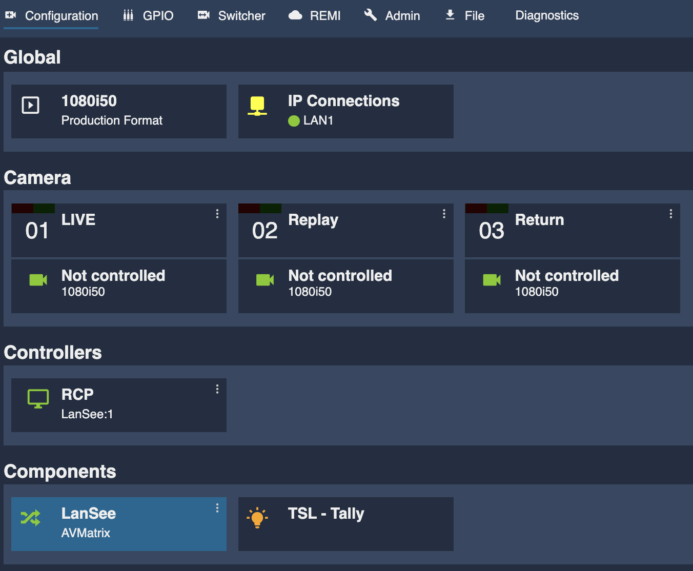
In addition to your existing camera/lens configuration, create 3 additional "not controlled" cameras. This will serve as a "virtual" camera to control the LanSee inputs.
In the Components section of the RCP web UI:
- Click on
+ - Select
Router/Switcher
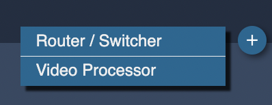
- Select
AVMatrix
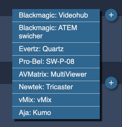
- And complete the informations (name, IP, link cameras, etc.)
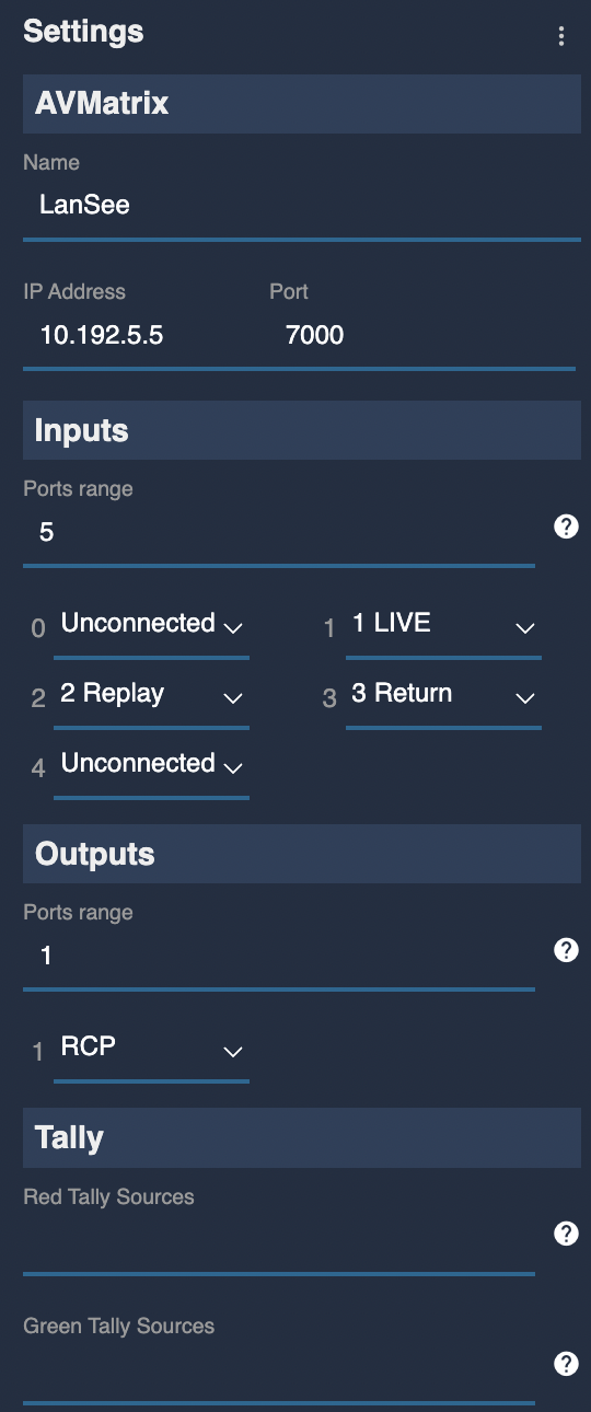
It should looks like this:
You can now follow this guide to configure the B4 lens buttons mapping.
You should now be able to press your lens buttons and toggle the video signal on the LanSee.