B4 Video Return
Overview
The goal is to use RET, VTR buttons on B4 lenses to be able to act on the video return from the switcher.
Camera set up
The first step is to configure the camera and the lens.
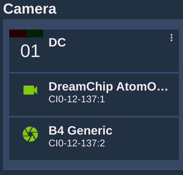
Here, I created a Dreamchip AtomOne with a Canon B4 lens:
- On the web UI
Configuration, inCamera, click on+ - Create your camera as usual, here I used a Dreamchip AtomOne
- Add your lens as usual, here I used
B4 Genericon my CI0-12-137, port 2
You can find more information:
Switcher set up
The second step is to configure the switcher and link my camera (configured above) to the correct input.
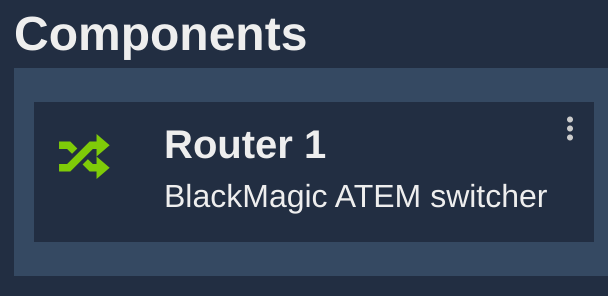
Here, I created an ATEM switcher and linked my camera DC to the input 1.
You can find more information on various switcher/router integration here.
Ensure the link is working, the block should be green:
Lens buttons link
Now, navigate to /dev/app.html. If my RCP is RCP-18-4 and I use the URL: http://10.192.18.4, then it is http://10.192.18.4/dev/app.html
Search for ATEM switcher (CTRL+F)
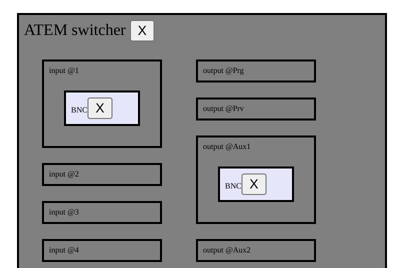
Click on the title, and you should see a panel on the right:
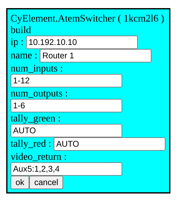
Set up the B4 video return by changing the field video_return (empty by default):
- It is a list, separated by
, - Each item in this list follows the syntax :
output:live_input,program_input,ret1_input,ret2_input - In this example:
Aux5:1,2,3,4means:Aux5: my monitor output on my ATEM1: my camera is on input 1, input 1 is displayed when no button is pressed2: input 2 is displayed when program button is pressed3: input 3 is displayed when RET1 button is pressed4: input 3 is displayed when RET2 button is pressed
Router input/output names
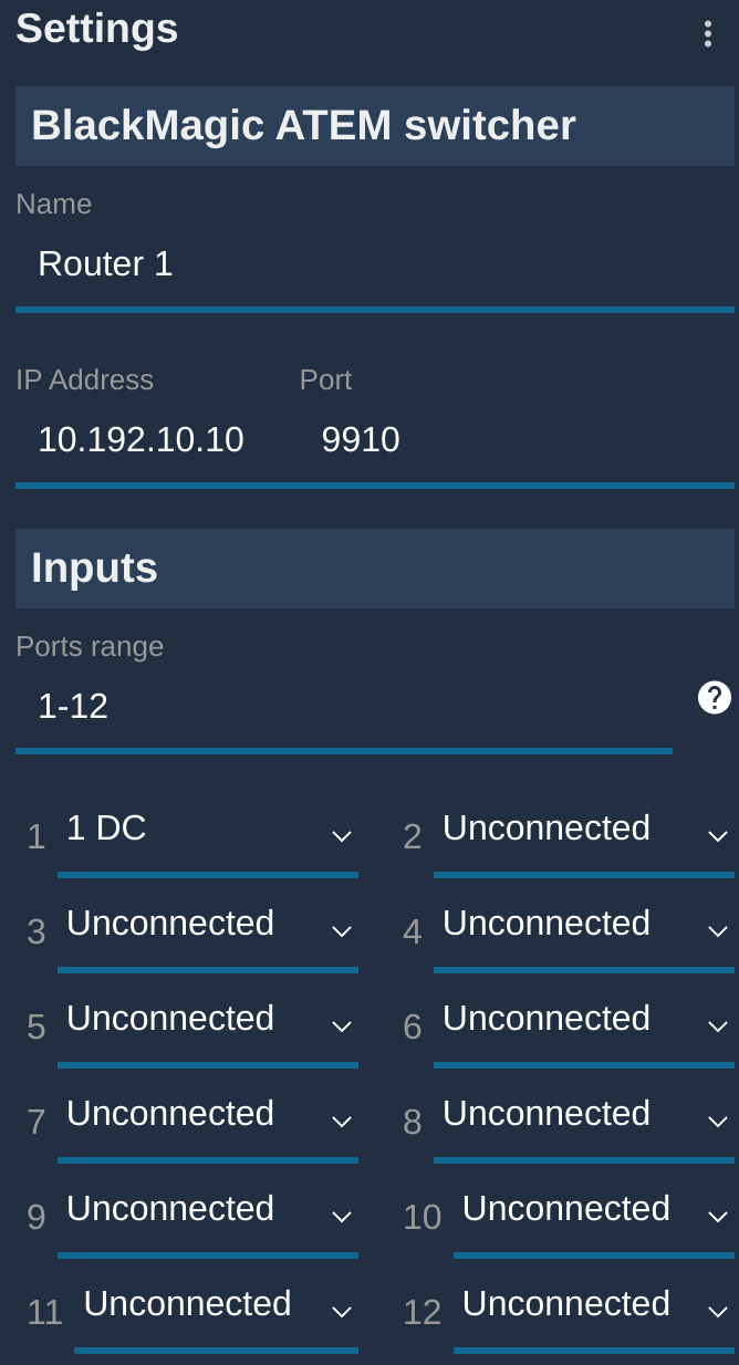
Refer to the configuration page of the RCP to ensure names match. Input/Output names are displayed in light grey.
ATEM:
- input names : 1, 2, ...
- output names : Aux1, Aux2, ...
VideoHub:
- input names : 1, 2, ...
- output names : 1, 2, ...
Troubleshooting
- Ensure your lens is properly configured. You can check by changing iris from RCP, you should read/write value.
- Ensure your camera is properly linked to the valid input in your switcher (this is how we link video_return numbers and cameras)
- Ensure your video_return is properly configured:
- input is in the input range of the router. If not, will be ignored. You can have input
21if your router input range is1-12 - output is in the output range of the router. If not, will be ignored. You can have output
Aux5if your router output range is1-4 - syntax is correct. You need all field, input/output separated by
:, 4 inputs separated by,and blocks separated by;
- input is in the input range of the router. If not, will be ignored. You can have input
- check on MQTT, you should see button press actions by subscribing to topic
+/+/camhead/action/set/video_return(you will see values likeret1,live, etc.)