Tally Input Configuration
Overview
Cyanview products have built-in tally routing capabilities.
Tally input:
- Pro-Bel SW-P-08 (VSM, etc.)
- ATEM
- TSL
- GPI (RCP/NIO)
Tally input
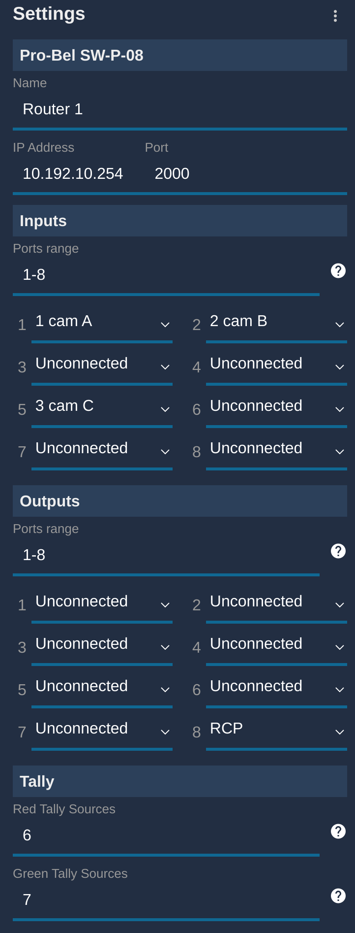
Pro-Bel SW-P-08
If you're using VSM, first configure it properly following this guide
- Link your camera to corresponding
inputs - Optional: link your RCP to an auxiliary
output - Configure which
outputis thelive(generates red tally) - Optional : configure which
outputis thepreview(generates green tally)
Here is an example:
- I have 3 cameras :
cam A(number 1),cam B(number 2) andcam C(number 3) cam Ais plugged oninput 1cam Bis plugged oninput 2cam Cis plugged oninput 5RCPis onoutput 8- Tally red is based on
output 6 - Tally green is based on
output 7
This will:
- Link the input of the corresponding camera with the
outout 8each time the camera is changed on the RCP - Generate a tally output to the corresponding camera when one of the camera (
cam A,cam Borcam C) is live - Generate a tally output to the corresponding camera when one of the camera (
cam A,cam Borcam C) is in preview
ATEM
First, configure your ATEM properly following this guide
Same concept as Pro-Bel/VSM setup described above
TSL
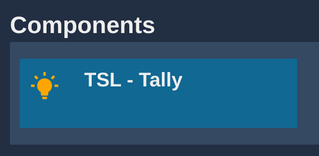
TSL is active by default. To configure it, select the block in the Components section.
The RCP works as a Multiviewer where the TSL display ID is the camera number. It supports TSL 3.1 and 5.0 in both UDP or TCP. It is a TSL server, so you have to add the RCP IP as being the IP of the screen in your TSL client manager (switcher, etc.).
If you click on the TSL block, you can change the default configuration:
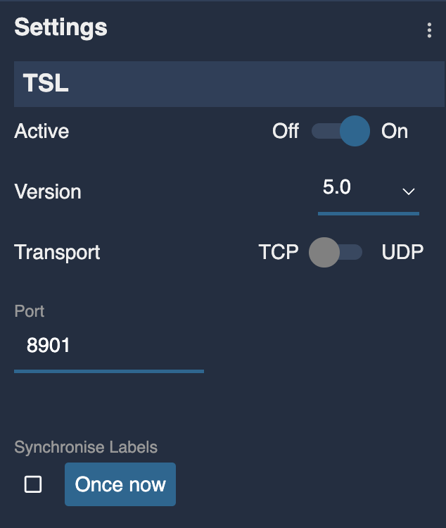
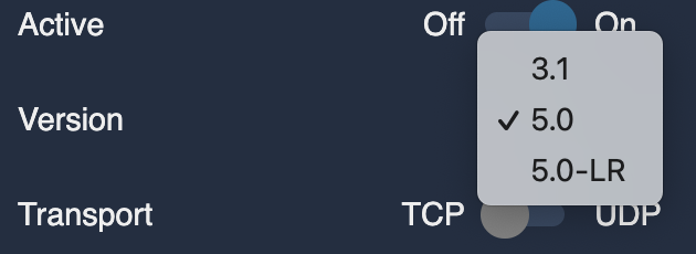
- Active: enable/disable the TSL server of the RCP
- Version:
- TSL 3.1 where TSL "Tally 1" bit is assigned to camera green tally, and TSL "Tally 2" bit is assigned to camera red tally. "Tally 3 and 4" bits are ignored.
- TSL 5.0: checks the Left and Right hand bits for the matching tally color. Red bit (0) or red bit (4) are assigned to camera red tally, green bit (1) or green bit (5) are assigned to camera green tally. Text tally state bits (2-3) are ignored.
- TSL 5.0-LR: any left hand tally bit (red or green) is assigned to camera red tally, and any right hand tally bit is assigned to camera green tally, independently of the color defined by the protocol. This is similar to TSL 3.1 which had no color definition. Ross or FOR-A TSL use this convention it seems.
- TSL 5.0-TXT: only text tally bits 2-3 are taken into account for the matching color, left and right bits are ignored.
- Transport: UDP or TCP
- Port: the port on which the RCP TSL server listens
- Synchronise Labels: renames the cameras with the TSL UMD labels. If the box is ticked, the names are continuously synchronized with the TSL labels. "Once now" will only update the names once with the labels that have been received so far.
Whether using TSL 3.1 or 5.0, the important point is to assign the camera number to the display index on the TSL client. TSL 3.1 only has a single index (possible named address) but TSL 5.0 has both a primary screen index and a display index. The screen index is ignored, the display index is used to match the camera number. In a multiviwer, this would correspond to the index of the video picture inside the multiview layout.
If TSL 5.0 doesn't seem to be working, check that the tally information is properly sent to either the Left Hand or Right Hand Lamp states and not the Text Tally state as this one is ignored. TSL preferences vary, some use green left, red right, others use both lamps to show red or green, while the text might always be red whether tally is red or green. This is the reason why we can't rely on the text tally bits to get the correct tally color.
GPI
Two use cases:
- If your GPIs are close to the RCP, you can connect CY-CBL-JACK-GPIO8 on your RCP
- If you want GPIO over ethernet/WiFi/4G, you can use a NIO
To setup:
-
Open the GPIO page of the RCP.
-
Associate the GPIO Inputs with your camera. Select Red Tally and click the cell at the intersection of the GPI row and CAMERA column.
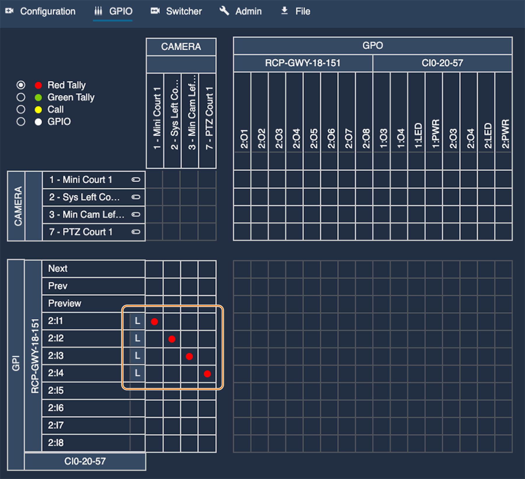
In this example:
GPI 1will trigger ared tallyon my camera1GPI 2will trigger ared tallyon my camera2GPI 3will trigger ared tallyon my camera3GPI 4will trigger ared tallyon my camera7
You can also control the input polarity:
- Set the input level (H-L) according to your wiring
- Click on L to toggle between H and L
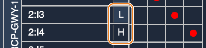
The CY-CBL-JACK-GPIO8 pins are default high. Select (L) to activate Tally at low polarity, and (H) for high polarity.
Green tally is configured the same way:
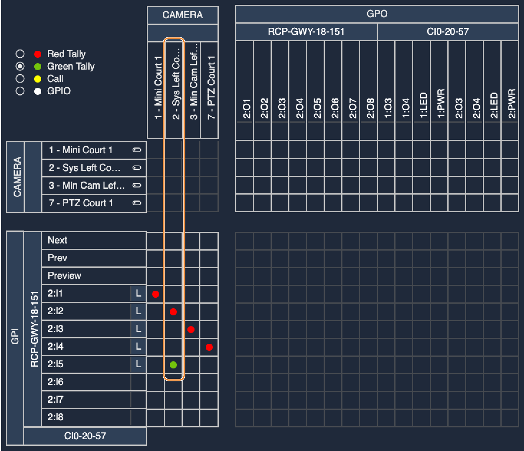
In this example:
GPI 2will trigger ared tallyon my camera2GPI 5will trigger agreen tallyon my camera2
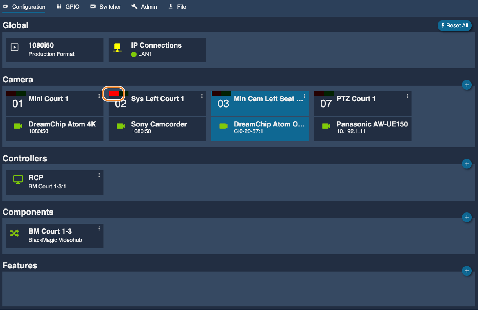
Tally status
In the RCP Web UI, the tally status is visible in the Configuration page.
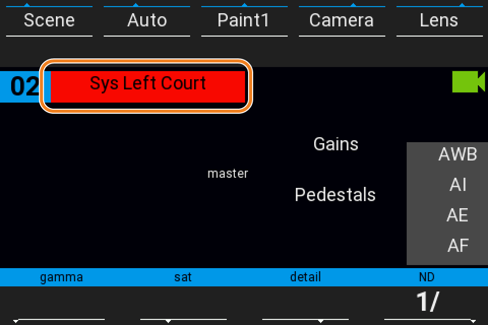
On RCP screen, the camera name background displays the tally color.