Preview / Touchdown
Overview
RCP touchdown or preview is a joystick or button push on the RCP that calls the right CCU output on the preview video monitor. This configuration only works when one camera is controlled by the RCP. In the case of multiple cameras, the configuration is slightly more complex and uses multiple GPIOs or an integration with a router protocol. The RCP will call the selected camera automatically when changing cameras or manually when pressing the preview button. In the other direction, if a camera is selected on the router panel (VSM, Cerebrum, Quartz, etc.) the RCP will automatically switch to that camera so the preview video and the RCP are always synchronized. Both directions work simultaneously so you can switch cameras either from the router panel or from the RCP. This makes it convenient to handle a large number of cameras on a single RCP or use the RCP as a master panel.
These are different options to configure camera touchdown:
- One camera on the RCP, using the preview button as a GPIO contact closure (RCP GPIO dongle)
- Multiple cameras on one RCP using the RCP GPIO dongle or the NIO (IP box with 16 GPIO)
- Multiple cameras using the router or switcher control protocol
- Using Ember+ camera selection (unofficial and undocumented, please contact us if you have a project requiring this)
GPIO interfaces: RCP dongle or NIO
For GPIO, 2 solutions are available:
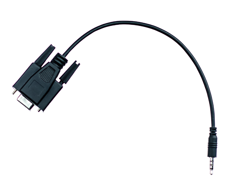
- CY-CBL-JACK-GPIO8 GPIO dongle that plugs at the back of the RCP and provides 8x GPIO that handles input and output at the same time. 2 units can be combined to provide 16x GPIO. See the link for the pinout. If only one camera is used, it uses the same pins as a Sony RCP on the DB9 connector so it can be plugged directly to the pre-wired installations in the desk where the RCP is installed.
- CY-NIO is a multi-purpose box that provides a 16 GPIO interface over IP. It is automatically detected by the RCP and is used in the same way as the GPIO dongle.
Configuration with one camera using a GPIO dongle or NIO
This configuration is similar to a standard RCP: a contact closure is linked to the press of the preview button. This is the desired behavior when the RCP only has one camera or when the preview button should be independent of the camera selection on the RCP.
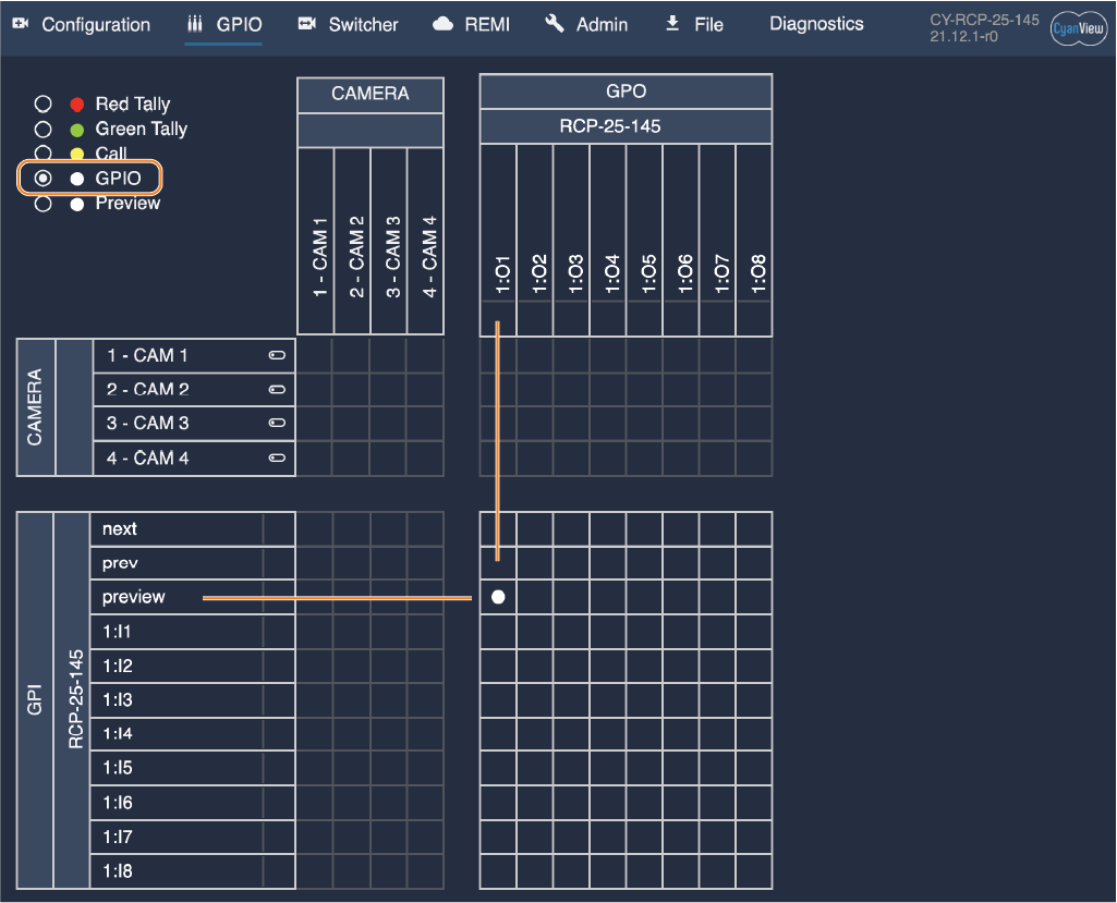
The configuration is done in the GPIO tab by selecting GPIO on the upper left. You can then link the preview button of the RCP on the left to the GPIO output on the top. When the preview button is pressed, the GPO will be driven low which is equivalent to a contact closure.
Configuration with multiple cameras using the GPIO dongle or NIO
When multiple cameras are configured on a single RCP, we need multiple GPIO to trigger each of the cameras. The trigger can be in any direction: the RCP can do contact closures to change the router input, or a router or an external push button could generate the contact closure that the RCP will receive as GPI to select another camera, or both simultaneously. This is the case when external buttons could change both the router and RCP selection, while the RCP could also generate a contact closure so the router will follow when the selection is done on the RCP itself.
Pulses are generated by default from the RCP. This allows switching the router from the RCP buttons, but also from a Streamdeck or the web GUI switcher tab.
Configuring the GPIO
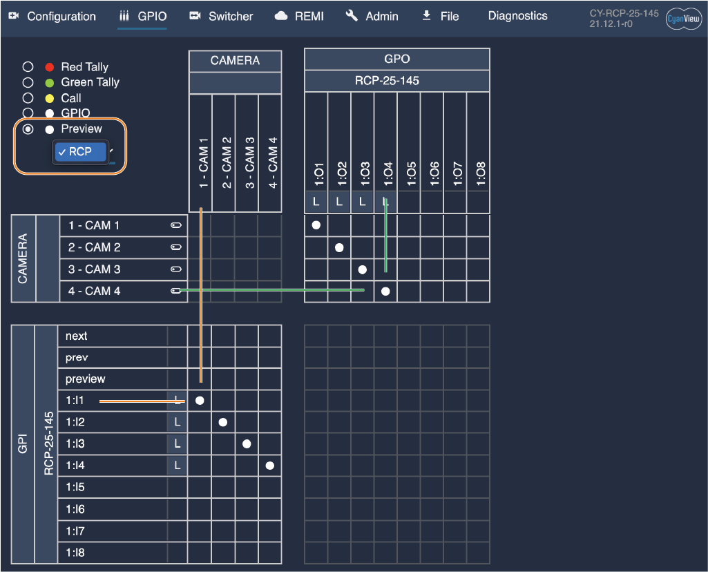
Select the Preview mode in the upper left corner and select the RCP in the drop-down list. The view will then show the mapping for that RCP with all the cameras available.
Adding a node from a GPI on the left to the cameras on the top (orange lines) will switch the RCP when a GPI is triggered. Adding a node on the right between a camera on the left and a GPO on the top will generate a pulse or level when the camera changes on the RCP or when the preview button is pressed.
Joystick Override Mode
Joystick Override means switching the router input to the selected camera while the preview button is pressed and held, and restoring the previous router input when the button is released.
There are two ways to use the RCP with a system that handles Joystick Override, such as typically used in the UK. One option is to use GPIO. The second is to configure a router integration to add a fallback route when the preview button is not pressed.
Joystick override using a router integration
This setup is described in our router integration section
Joystick override using GPIO
If you control only a single camera from the RCP, the simplest option is to use the PREVIEW button state directly. This state can be routed from the GPIO page to any GPIO output and behaves like a classic contact closure on a traditional RCP.
When the RCP is configured for multiple cameras and used with a system that handles Joystick Override over GPIO, the RCP should generate one GPIO signal per camera, using levels instead of pulses. In this mode, the PREVIEW button holds the corresponding camera’s GPIO “closed” for as long as the button is pressed. The RCP itself does not perform the override; it behaves like a standard RCP so that external systems such as VSM, Cerebrum, or dedicated joystick-override boxes can manage the router.
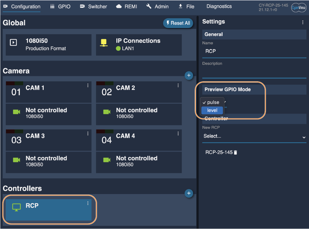
To switch from pulse mode to level mode, open the controller set properties (main tab, controller section) and change the preview GPIO behavior to “Level”. All preview-related GPIO actions for that controller will then use levels instead of pulses.
Synchronization with a router or switcher protocol
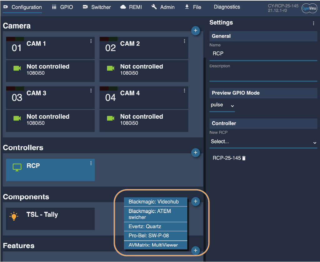
An alternative to GPI is to use the router control protocols to synchronize camera selection on the RCP and on the preview video monitor. This is done on the main configuration tab in the components section. Refer to the integration guides for each equipment or protocol.
Typically, the integration module will assign a router output to the RCPs controller set, and assign a router input to any known camera. When the router switches the input on that preview monitor, the RCP will automatically change to the corresponding camera. And when the camera is changed on the RCP, it will switch the router to that corresponding video input. This ensures that the RCP camera selection will always match the camera displayed on the preview monitor.
RCP options for preview and auto-selection
The RCP has a few options available on the LCD interface itself to change the behavior of the preview function when switching cameras. These are under MENU > Settings.
- Follow Router Selection: the RCP will automatically change the camera when a GPI or a router changes the input. This can be disabled if you want to temporarily hold the RCP to one camera.
- AUTO preview on camera change: when using the arrow keys on the RCP to change the camera, a preview pulse will be automatically generated on the GPO or the router will change to the new camera source. If this is disabled, cameras can be changed on the RCP but pressing preview is then necessary to change the router or generate the GPO pulse.
- Disable Pre/Next keys: when one RCP is used per camera, or if an external router panel or Streamdeck is used to change cameras on the RCP, it is possible to disable the arrow keys in which case all 3 keys will act as the preview button.
- Access all cameras: this is an advanced configuration where one RCP can be restricted to a subset of cameras. This option allows temporary access to all cameras. Note: This feature isn't yet integrated in the GUI and will be available in a future release