GPIO Dongle
GPIO dongle extension for tally or preview/touchdown
The CY-CBL-JACK-GPIO8 is an extension dongle that plugs at the back of the RCP and provides 8 inputs/outputs on a DB9 connector. Up to 2 dongles can be connected for a total of 16 GPIO.
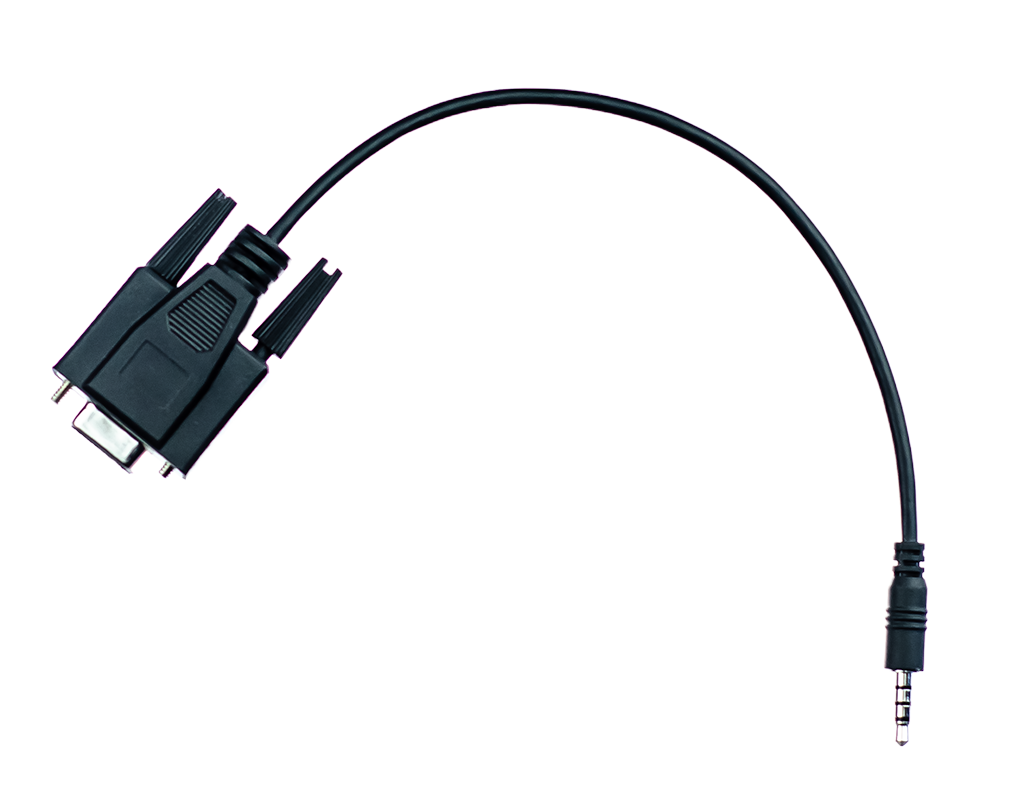
- The 3.5mm jack connects to the back of the RCP.
- GPIO are accessible on the DB9 connector.
The dongle can be used to acquire tally inputs or can output preview/touchdown signals. Each GPIO are independent and can be configured as input or output from the GPIO page of the configuration web interface.
pinout

-
When a GPIO is used as input :
- It can be connected directly to a dry contact closure circuit. Internal 10k pull-up resistors to 5V are provided.
- Connection to an active contact is supported. The voltage should remain below 5V, and the connection should be made relative to ground. No internal protection against polarity reversal is provided.
-
When the GPIO is used as output :
- The HIGH state voltage is 5V, with a maximum output current of 500uA
- The LOW state voltage is 0V, with a maximum input current of 25mA
It is now frequent to use a common GND for signaling. Care must be taken to connect the GND of multiple equipments together otherwise an input pin might appear as permanently activated (contact closed) on either the RCP or the other equipment such as a router.
Simple 2 GPIO version
A simpler version providing only 2 GPIO can be made following this pinout.
This simple version can only provide 2 GPIO on port 1, and port 2 has to be disabled for this simple version so make sure to only plug a single cable to port 1 which is the port closer to the edge of the RCP. This provides a simple and unexpensive option to have one pin for touchdown and one for tally to each RCP.

The GPIO will be read or pulled low with a non-isolated driver IC. The common GND of the 2 pins is also the GND of the RCP power supply and chassis. If the connected equipment is not isolated, it is required to use a common GND for signaling. Care must be taken to connect the GND of multiple equipments together otherwise an input pin might appear as permanently activated (contact closed) on either the RCP or the other equipment such as a router.
-
When a GPIO is used as input :
- It can be connected directly to a dry contact closure circuit. Internal 4.7k pull-up resistor to 5V is provided.
- Connection to an active contact is supported. The voltage should remain below 5V, and the connection should be made relative to ground. No internal protection against polarity reversal is provided.
-
When the GPIO is used as output :
- The HIGH level is pulled up to 5 V through a 4.7 kΩ resistor, allowing for a maximum output current of 1 mA.
- The LOW level is pulled to 0 V through a transistor, allowing for a maximum input current of 25 mA.
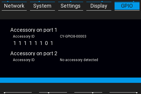
Status
The GPIO dongle can be monitored from the RCP screen by using the Menu button then select the GPIO Menu tab.
Configuration
The configuration is done via the GPIO page of the RCP Configuration Web UI. For tally, more information is available here: Tally configuration.
Fanout cable for tally and touchdown
This cable is not available for sale
Here is an example pinout of a fanout cable to provide one tally on XLR and one touchdown on DB9 from a single dongle. This can be extended to provide more channels by simply connecting more connectors to the other GPIO pins available. Make sure the common pin GND used on all connectors is also the GND of the equipment it will be connected to as it is quite common today to have GPI that are not fully isolated.
