CI0 Manual
This page covers the generic CI0 characteristics and configurations. Specific guidance for supported cameras and devices configuration can be found in the Integration section.
CI0 Ports
Serial Ports
Connectors
Serial ports connector refererence: Hirose HR10A-7R-6S(73)
Mating plug for cables: HR10A-7P-6P(73)
Cyanview provides a range of cables to interface most cameras. Please refer to our cable page.
The Integration manuals also provide information on what cable to use for what camera.
Port Pinout
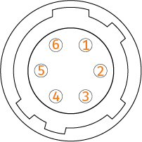 Female receptacle. | PIN Number | Protocol Pinouts | ||
|---|---|---|---|---|
| RS232 | RS422 | RS485 | ||
| 1 | Y/TX+ | A/+ | ||
| 2 | TX | Z/TX- | B/- | |
| 3 | RX | A/RX+ | ||
| 4 | B/RX- | |||
| 5 | GND | GND | GND | |
| 6 | +12V | +12V | +12V | |
| Shell | ||||
CI0 Models
Different CI0 models differentiates on number and type of ports:
- CY-CI0: Standard two ports.
- CY-CI03P: A third ports available for cam head management.
- CY-CI0BM: CI0 two ports with BlackMagic SDI control extension (see: BM serial cam integration manual).
Supported protocols
Different CI0 Ports will support different protocols:
| Port/Protocol | RS485 | RS232 | RS422 | LANC | SBUS | VISCA | B4 Lens |
|---|---|---|---|---|---|---|---|
| P1 | V | V | V | V | V | ||
| P2 | V | V | V | V | V | V | V |
| P3 | V |
Ethernet Port
10/100Mb Ethernet, PoE+ (Power over Internet) 802.3af/at
Supported Serial topology
A serial camera connected to CI0
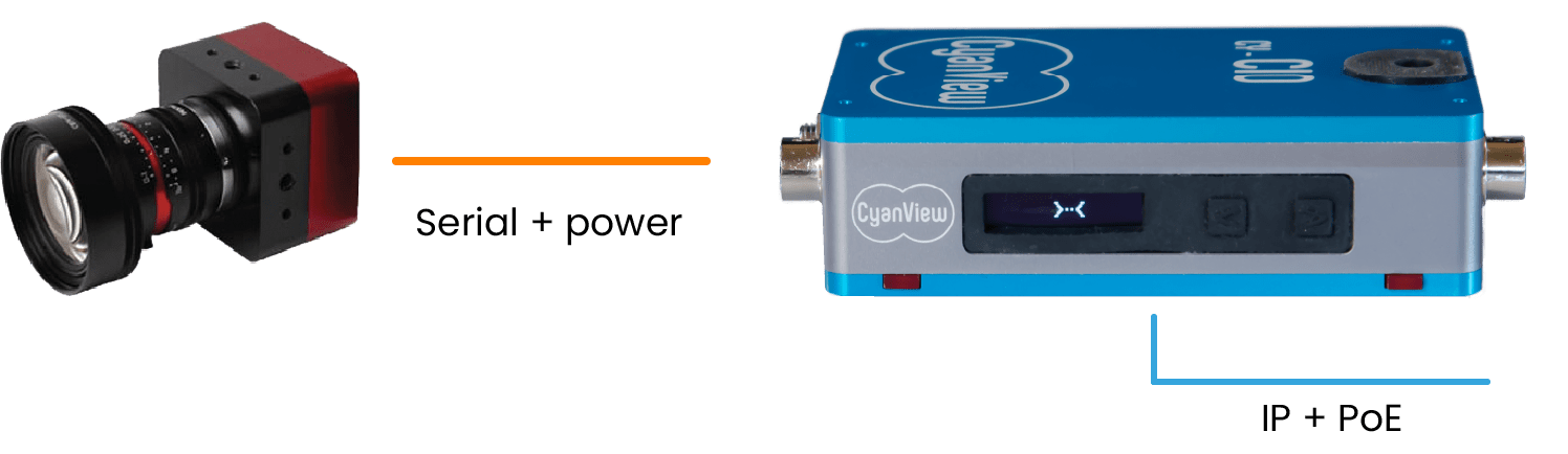
- Basic configuration where CI0 turns a camera into managed camera.
A camera on each port
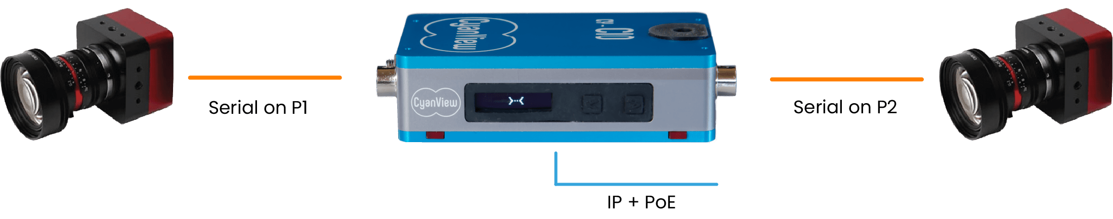
- Several Serial camera connected to CI0.
- One serial camera by port.
- Two ports available on base CY-CI0 model, three ports available on CY-CI03P.
A BUS of cameras
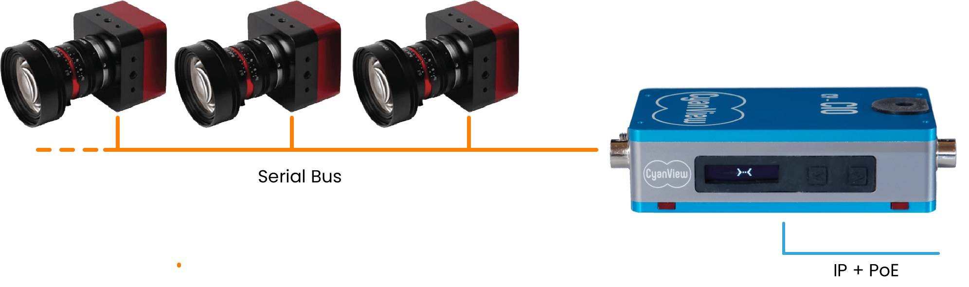
- When camera supports Serial BUS, several camera can be connected on a single port (see: CI0 Serial BUS).
Connection and Setup
Network setup
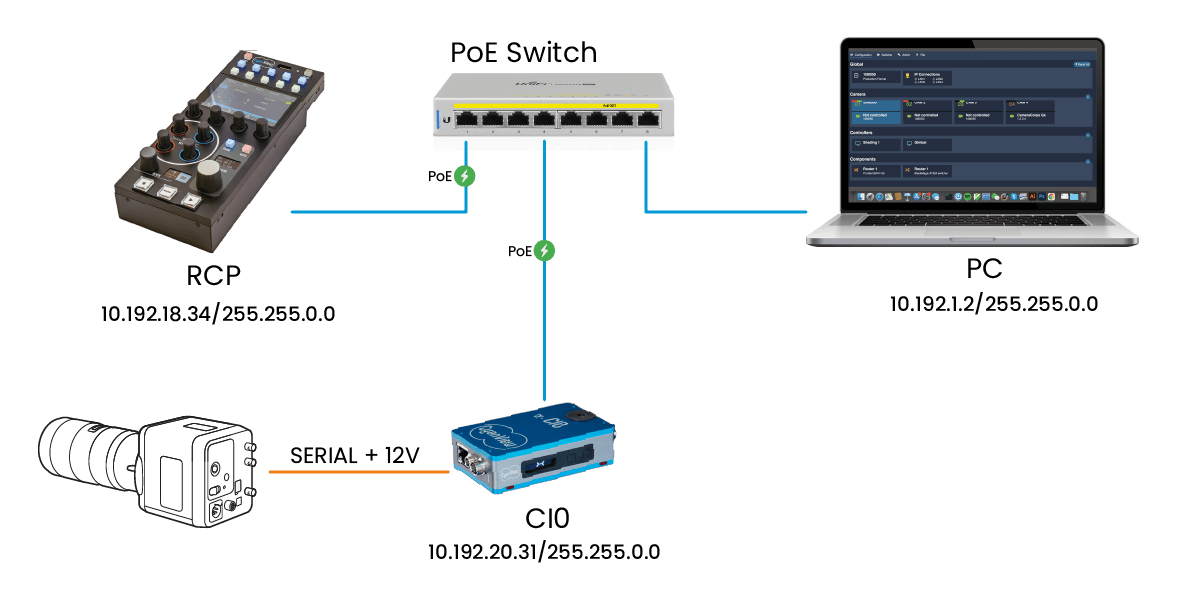
The CI0 has been designed to be plug and play and avoid conflicts. As such, IP addresses are fixed based on the serial number, and a discovery process makes the CI0 appear automatically on the RCP interface.
Required ports
CI0 relies on TCP/IP network with no port limitation in order to communicate with other devices.
Mandatory ports:
- 3838 UDP port for discovery.
- 1883 TCP port.
- Random port for serial communication.
WiFi

By using a TPLink nano router, you can control your camera over WiFi. You can follow this guide to guide you through the setup.
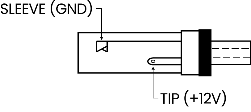
Power Connection
The CI0 can be powered through PoE+ or an external 12V 2A DC power supply.
When powered with PoE, the output voltage on ports connectors will be 12V DC, regulated. When powered with the DC IN plug, the voltage is not regulated. Thus, the input voltage will be present on the 2 camera ports. Make sure that the cameras connected support the voltage you supply on DC IN.
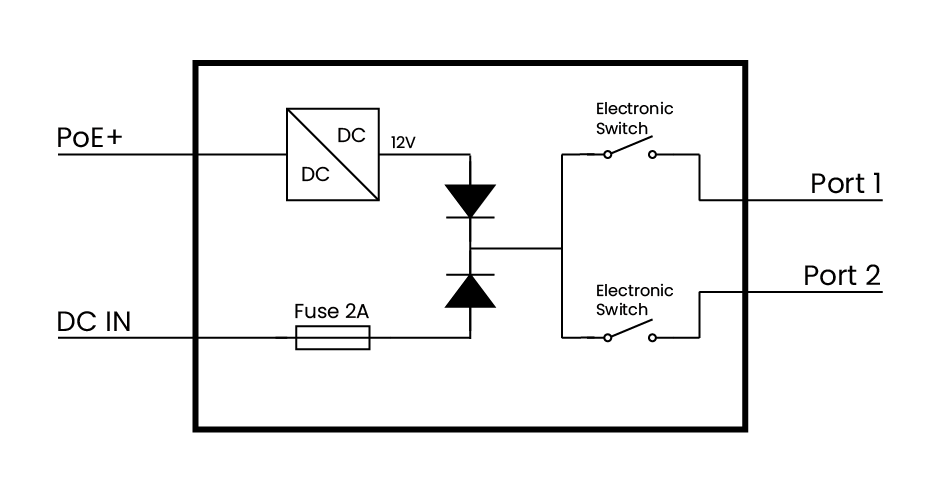
- DC IN voltage is between 10V and 24V. The input voltage will be directly applied to the camera so if you power from batteries, make sure the camera does support the higher battery voltage as well. For thermal reasons, camera consumption should not exceed 12W by port.
- When using PoE+, the power provided to the camera is 12V 1A, depending on the network switch. For most mini-cameras, regular PoE is enough and PoE+ isn't necessary.
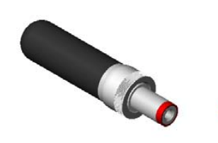
The power plug is a switchcraft 762K or compatible (5.5x2.1mm) with a locking screw. D-TAP to DC locking screw cables are easily found in online shops. To build custom cables, another option is to use the Digikey 10-00110 cable cut in half.
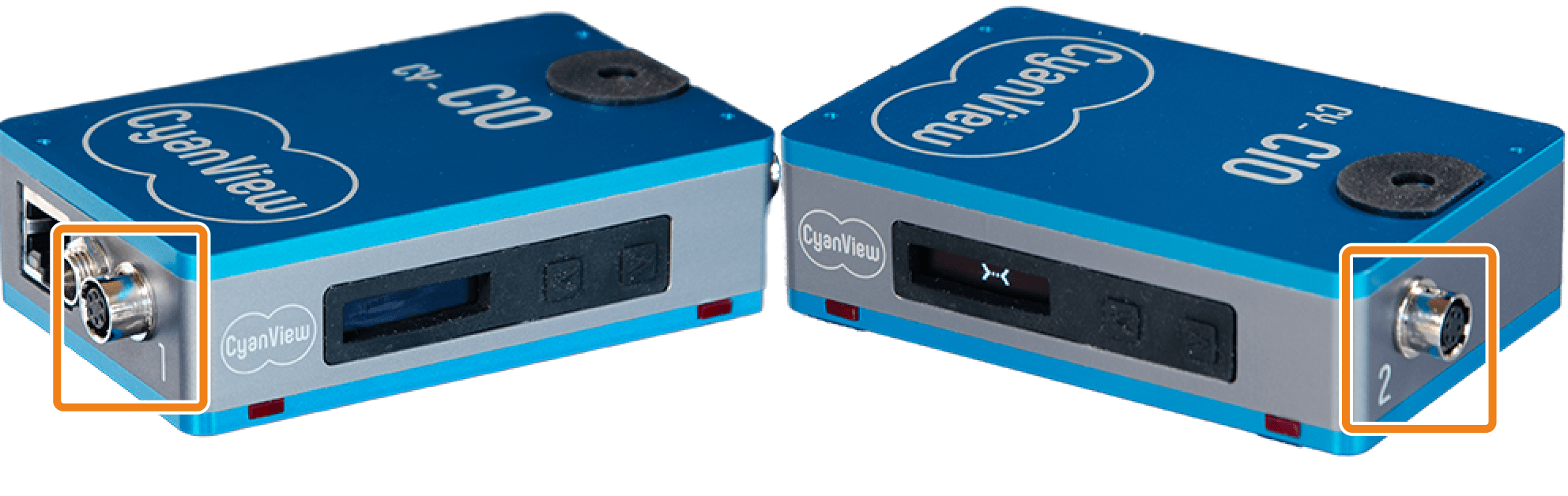
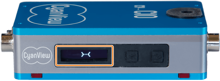
CI0 status
CI0 network connectivity status is displayed on the lateral LCD screen.
Status:
 CI0 is waiting for network connection.
 CI0 is connected to the network but not RCP.
 CI0 is discovered by an RCP.
 Camera 01 is configured on port 1 but not connected to CI0.
 Camera 01 connected to CI0.
In this example, status screen shows that camera 01 is configured on Port 1 (left), if camera is configured on port 2 (right), the camera number would be displayed on the right side
 .
.
When using a CY-CI03P, the third port status is displayed in the middle:

When pushing one of the button aside the screen, the screen will loop the following information: Camera name on PORT1, PORT2, CI0 IP address, CI0 MAC address. The screen will display the default information after a few seconds.
Update
CI0 is updated automatically by the RCP or GWY when the software version changes. This ensures that the firmware is always synchronized with the corresponding software. If the CI0 firmware version doesn't match the version required by the RCP, the CI0 will be updated at startup.
Troubleshooting
You can find typical issues and solution in this dedicated section
CI0 doesn't start
A working CI0 should have:
- RJ45 steady green LED (operating at 100-Mbps)
- RJ45 blinking orange LED (activity on the link)
- screen showing
>-<or<->with numbers
- Check your wiring. Eventually put your CI0 and RCP/GWY on the same switch.
- Perform a config reset of your RCP/RIO/GWY. To check that the CI0 is detected properly.
- If you're in PoE, try using a 12V DC power supply.
- If you're already using a 12V DC power supply, try another one.
Force a firmware update
It is possible to force a CI0 firmware update.
Ensure to have a RCP/GWY/RIO on the same network.
- Hold the 2 buttons pressed while you power it
- Release after 5 seconds
- If the LEDs blink, then it's in bootloader.
- After maximum 1 minute it should come back to life and display
>-<
Power supply issues
If your camera control sometimes drops or if your camera reboots continuously. Try to switch from PoE to a dedicated power supply.
On some camera (Dreamchip ATOM 4K with a motorised lens for example), the init power spike can be "too much". Use a dedicated power supply for your camera.
If you have multiple camera plugged on the same CI0, try to remove them all and plug them one by one.
CI0 screen 'X'
CI0 can't communicate with RCP/RIO over the network.
- Check your wiring
- Verify network connections: activity on the green and yellow LED of ethernet port.
- Make sure 3838 UDP port is not blocked.
Camera not powered and screen is dark
This is a bug on old CI0 with software 21.10