Tally Configuration
Overview
Tally information can be distributed to cameras via the RCP and other Cyanview devices, based on data received from the video switcher. Typically, tally is ingested using the TSL protocol or through direct integration with supported switchers. It is then relayed to the cameras either through the control protocol or sent to an external tally light.
Tally data follows the same routing as camera control signals — whether transmitted locally between RCPs or distributed remotely via the REMI cloud through a RIO. Any device within the system can ingest tally data, and this information is then automatically shared across all connected devices, both locally and remotely.
There are different ways to ingest tally:
Tally can be output with the following methods:
- Camera protocol if supported (Panasonic UE150, Sony PMW-500, etc.)
- GPO (RCP/NIO)
- Embedded LED (CI0/RIO)
- External LED (CI0/RIO)
Tally input
TSL
RCP and other Cyanview devices (RIO, NIO) include a built-in TSL server that acts as a multiviewer. In this setup, each camera in your RCP configuration is assigned a TSL display ID that matches its camera number. This allows the TSL protocol to simultaneously receive tally information for all configured cameras through a single connection.
The RCP supports TSL versions 3.1 and 5.0 over both UDP and TCP protocols. Since the RCP acts as a TSL server, you must configure your TSL client (switcher, etc.) to use the RCP's IP address as the screen/display IP address.
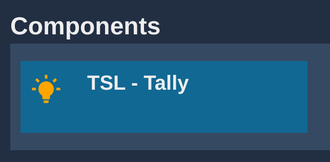
TSL is active by default. To configure it, select the block in the Components section.
If you click on the TSL block, you can change the default configuration:
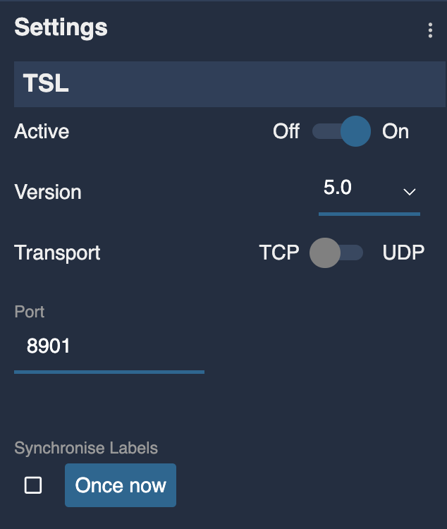
- Active: enable/disable the TSL server of the RCP
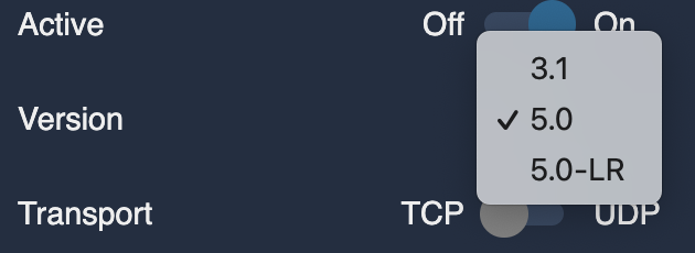
- Version:
- TSL 3.1 where TSL "Tally 1" bit is assigned to camera green tally, and TSL "Tally 2" bit is assigned to camera red tally. "Tally 3 and 4" bits are ignored.
- TSL 5.0: checks the Left and Right hand bits for the matching tally color. Red bit (0) or red bit (4) are assigned to camera red tally, green bit (1) or green bit (5) are assigned to camera green tally. Text tally state bits (2-3) are ignored.
- TSL 5.0-LR: any left hand tally bit (red or green) is assigned to camera red tally, and any right hand tally bit is assigned to camera green tally, independently of the color defined by the protocol. This is similar to TSL 3.1 which had no color definition. Ross or FOR-A TSL use this convention it seems.
- TSL 5.0-TXT: only text tally bits 2-3 are taken into account for the matching color, left and right bits are ignored.
- Transport: UDP or TCP
- Port: the port on which the RCP TSL server listens
- Synchronise Labels: renames the cameras with the TSL UMD labels. If the box is ticked, the names are continuously synchronized with the TSL labels. "Once now" will only update the names once with the labels that have been received so far.
Whether using TSL 3.1 or 5.0, the important point is to assign the camera number to the display index on the TSL client. TSL 3.1 only has a single index (possible named address) but TSL 5.0 has both a primary screen index and a display index. The screen index is ignored, the display index is used to match the camera number. In a multiviwer, this would correspond to the index of the video picture inside the multiview layout.
If TSL 5.0 doesn't seem to be working, check that the tally information is properly sent to either the Left Hand or Right Hand Lamp states and not the Text Tally state as this one is ignored. TSL preferences vary, some use green left, red right, others use both lamps to show red or green, while the text might always be red whether tally is red or green. This is the reason why we can't rely on the text tally bits to get the correct tally color.
GPI
Two use cases:
- If your GPIs are close to the RCP, you can connect CY-CBL-JACK-GPIO8 on your RCP
- If you want GPIO over ethernet/WiFi/4G, you can use a NIO
To setup:
-
Open the GPIO page of the RCP.
-
Associate the GPIO Inputs with your camera. Select Red Tally and click the cell at the intersection of the GPI row and CAMERA column.
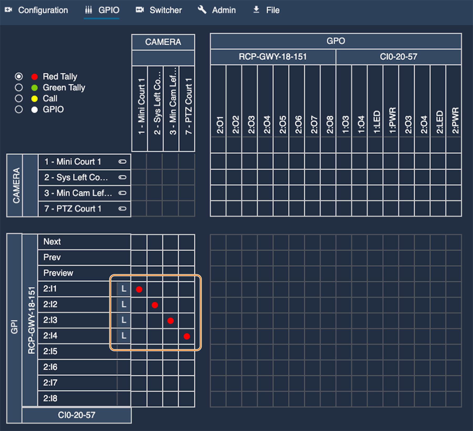
In this example:
GPI 1will trigger ared tallyon my camera1GPI 2will trigger ared tallyon my camera2GPI 3will trigger ared tallyon my camera3GPI 4will trigger ared tallyon my camera7
You can also control the input polarity:
- Set the input level (H-L) according to your wiring
- Click on L to toggle between H and L
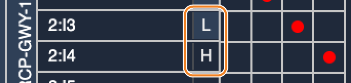
The CY-CBL-JACK-GPIO8 pins are default high. Select (L) to activate Tally at low polarity, and (H) for high polarity.
Green tally is configured the same way:
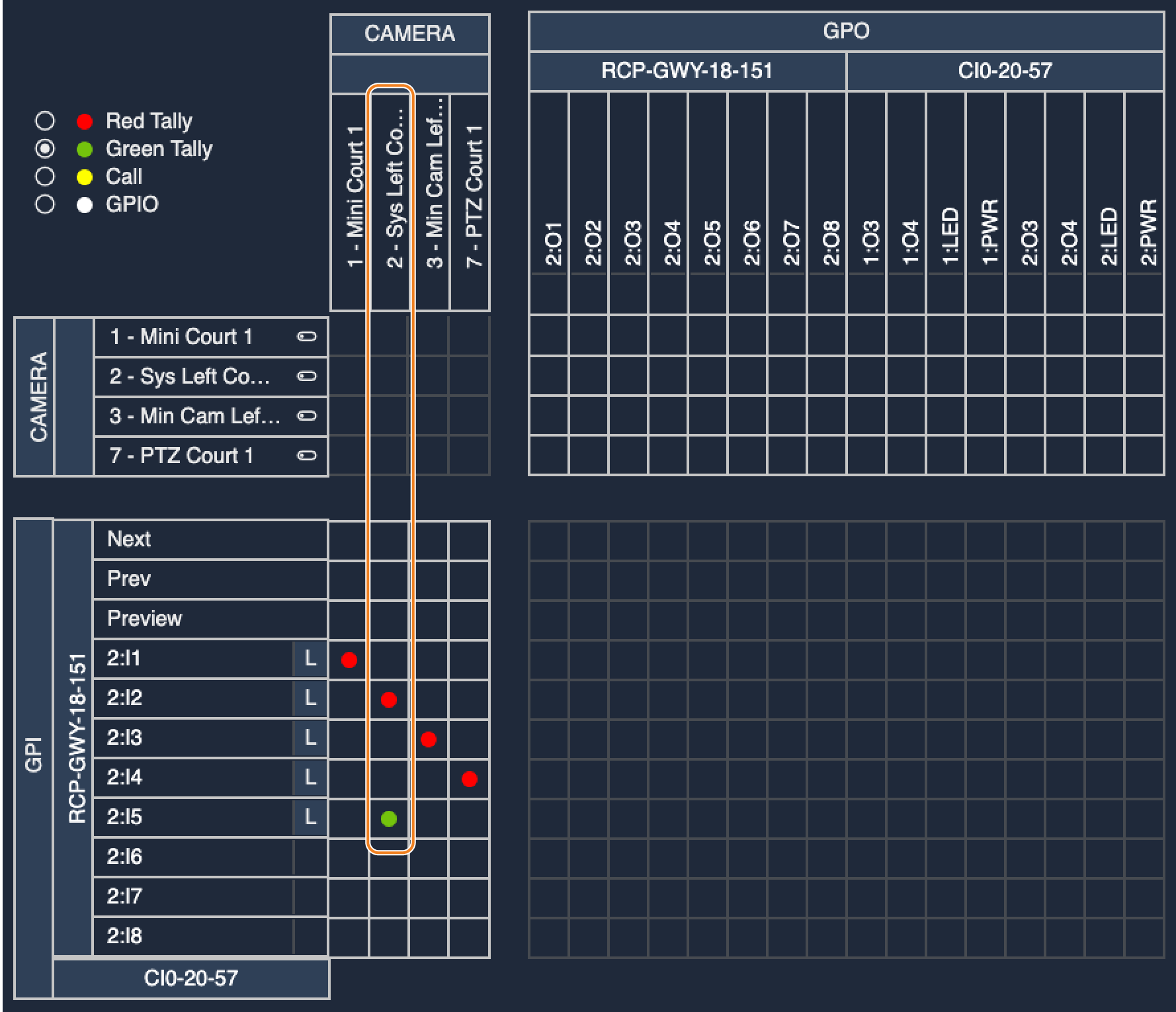
In this example:
GPI 2will trigger ared tallyon my camera2GPI 5will trigger agreen tallyon my camera2
ATEM
First, configure your ATEM properly following this guide
Same concept as Pro-Bel/VSM setup described below
Pro-Bel SW-P-08
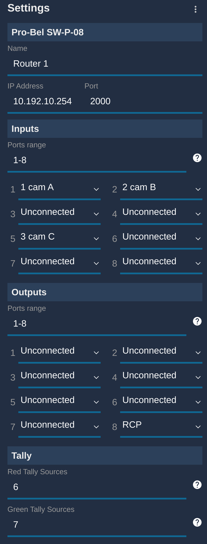
If you're using VSM, first configure it properly following this guide
- Link your camera to corresponding
inputs - Optional: link your RCP to an auxiliary
output - Configure which
outputis thelive(generates red tally) - Optional : configure which
outputis thepreview(generates green tally)
Here is an example:
- I have 3 cameras :
cam A(number 1),cam B(number 2) andcam C(number 3) cam Ais plugged oninput 1cam Bis plugged oninput 2cam Cis plugged oninput 5RCPis onoutput 8- Tally red is based on
output 6 - Tally green is based on
output 7
This will:
- Link the input of the corresponding camera with the
outout 8each time the camera is changed on the RCP - Generate a tally output to the corresponding camera when one of the camera (
cam A,cam Borcam C) is live - Generate a tally output to the corresponding camera when one of the camera (
cam A,cam Borcam C) is in preview
Tally status
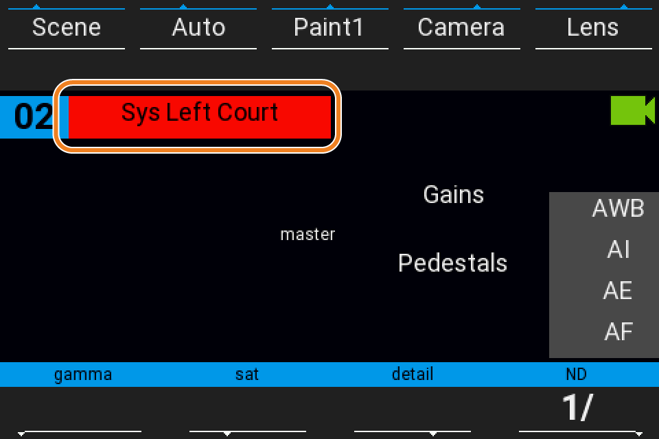
In the RCP Web UI, the tally status is visible in the Configuration page.
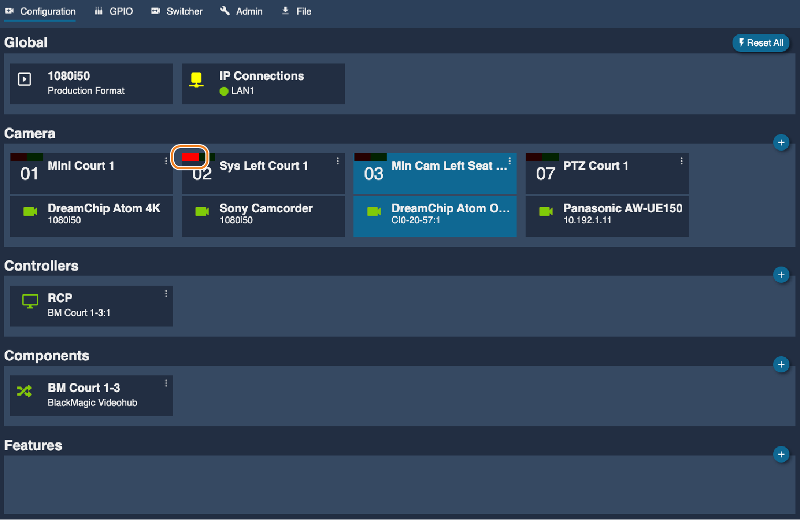
On RCP screen, the camera name background displays the tally color.
Tally Output
Camera protocol
For cameras that support tally through their control protocol, the RCP automatically sends tally information directly to the camera without requiring any additional hardware or configuration. This is the most seamless method as it leverages the existing camera control connection.
How it works:
- Tally data is embedded within the camera control protocol commands
- The camera's built-in tally system (viewfinder, recording indicator, etc.) responds automatically
- No additional wiring or external tally devices are needed
- Tally follows the same connection path as camera control
Supported cameras include:
- Panasonic UE-150, UE-70, UE-100
- Sony PMW-500, PMW-300, PXW-Z450
- Blackmagic MicroStudio cameras
- JVC cameras with compatible protocols
The tally behavior depends on the camera's implementation - some cameras display tally on the viewfinder, others may activate recording indicators or both. Refer to your camera's documentation for specific tally display capabilities.
GPO
Two use cases:
- If your GPIs are close to the RCP, you can connect CY-CBL-JACK-GPIO8 on your RCP
- If you want GPO over ethernet/WiFi/4G, you can use a NIO
In any case, each pin can either be used as GPI or GPO.
CI0/RIO embedded LED
By default, they display the tally signal on the LED of their casing.
They have one LED per port, 1:LED for the LED of port 1, 2:LED for the LED of port 2.
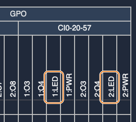
CI0/RIO external LED
If you have one camera on port 1, you can use the second port as an external tally output (12V).
Use the CY-CBL-6P-PWR cable to drive a Tally signal.

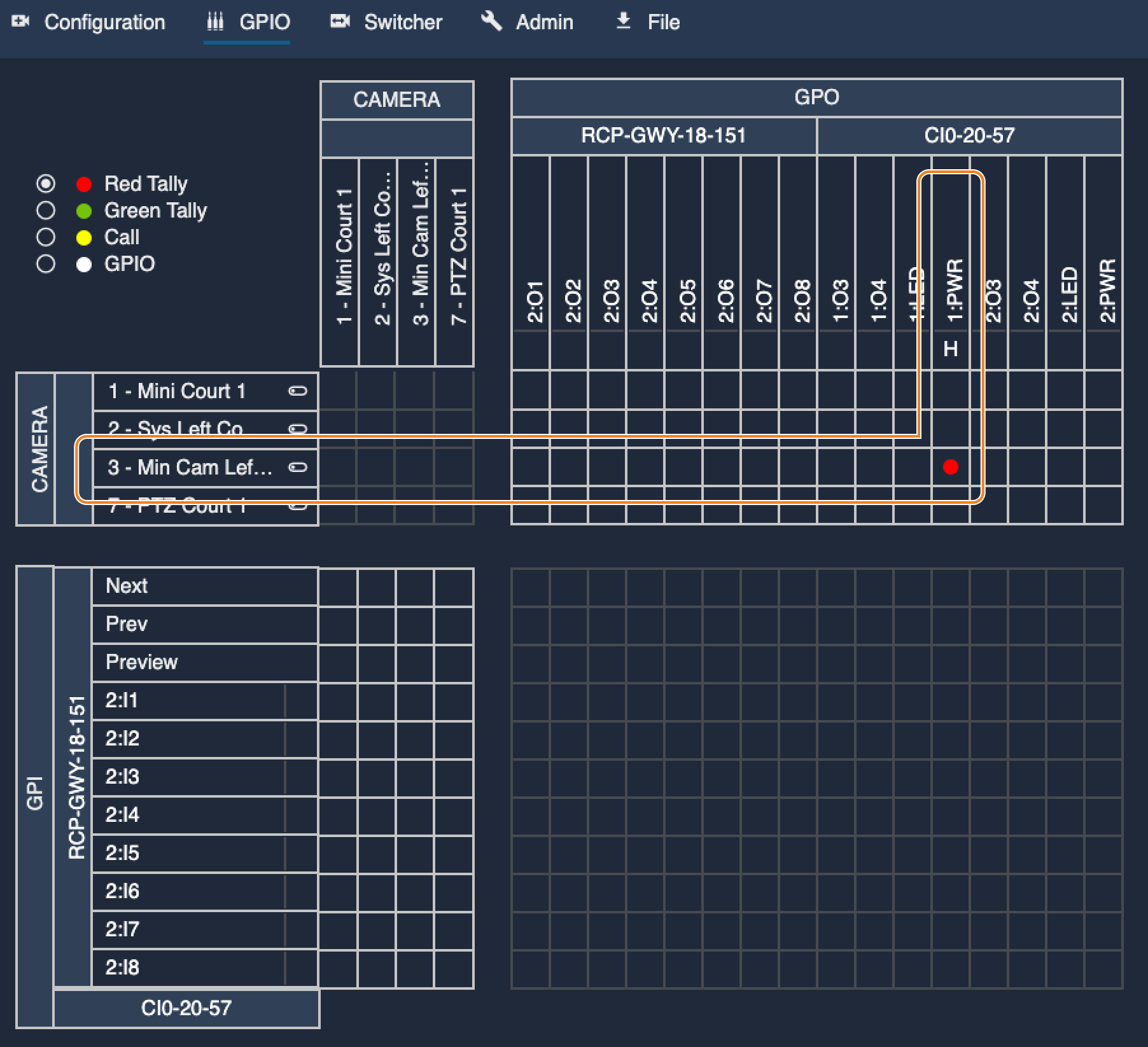
In this example the when camera 3 receives a red tally input, it will toggle the 12V of port 1 of CI0-20-57
Tally on Monitor
Overview
This section explains how to output a tally signal to a monitor, indicating the tally status of the currently selected camera on the monitor. The tally updates dynamically, following camera changes on the monitor in real time.
This is based on the assumption that your RCP is configured on a router/switcher. Linked to an auxiliary output. And that you can switch camera on the RCP (or push preview button) and the switcher/router auxiliary output follows.
Goal
By following this guide, you will have:
- Tally input from your ATEM (red/green tally is displayed on RCP and web UI)
- RCP sync active camera with
AUX1of your ATEM (visible on your monitor) - If the active camera is
- live, your monitor will light
red - preview, your monitor will light
green
- live, your monitor will light
Wiring
Connect on the same LAN your RCP's and your NIO's.
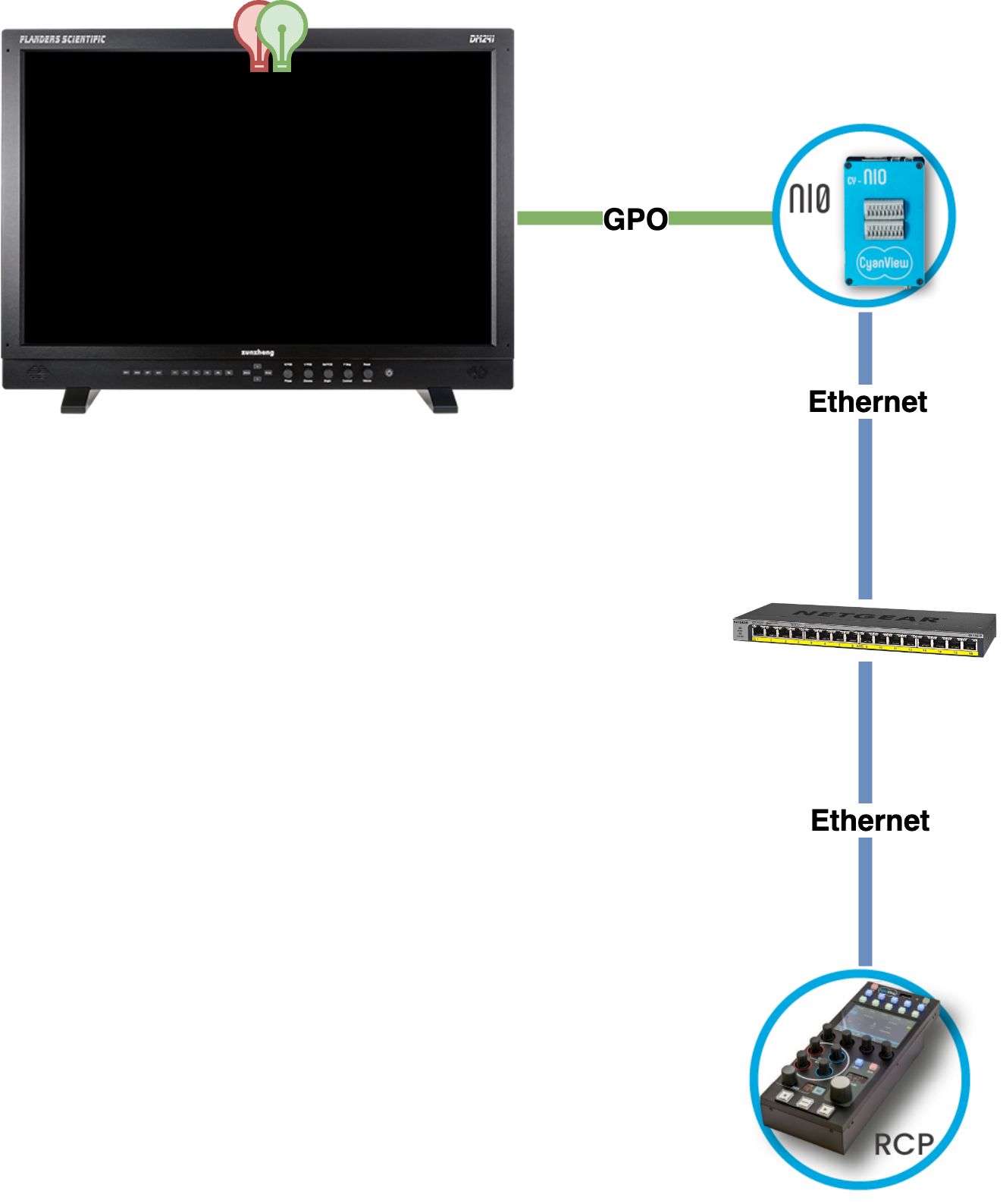
Instead of a NIO, you can use GPIO dongles plugged directly in the RCP
Setup
Overview
The goal here is to have a proper tally input and sync your RCP with your monitor.
In this example, I'll use an ATEM. But the same concept applies to any switcher/router.
I have here:
- 3 cameras (
cam 1,cam 2andcam3) - 1 RCP in a
virtual monitor(D1) - 1 ATEM (
ATEM)
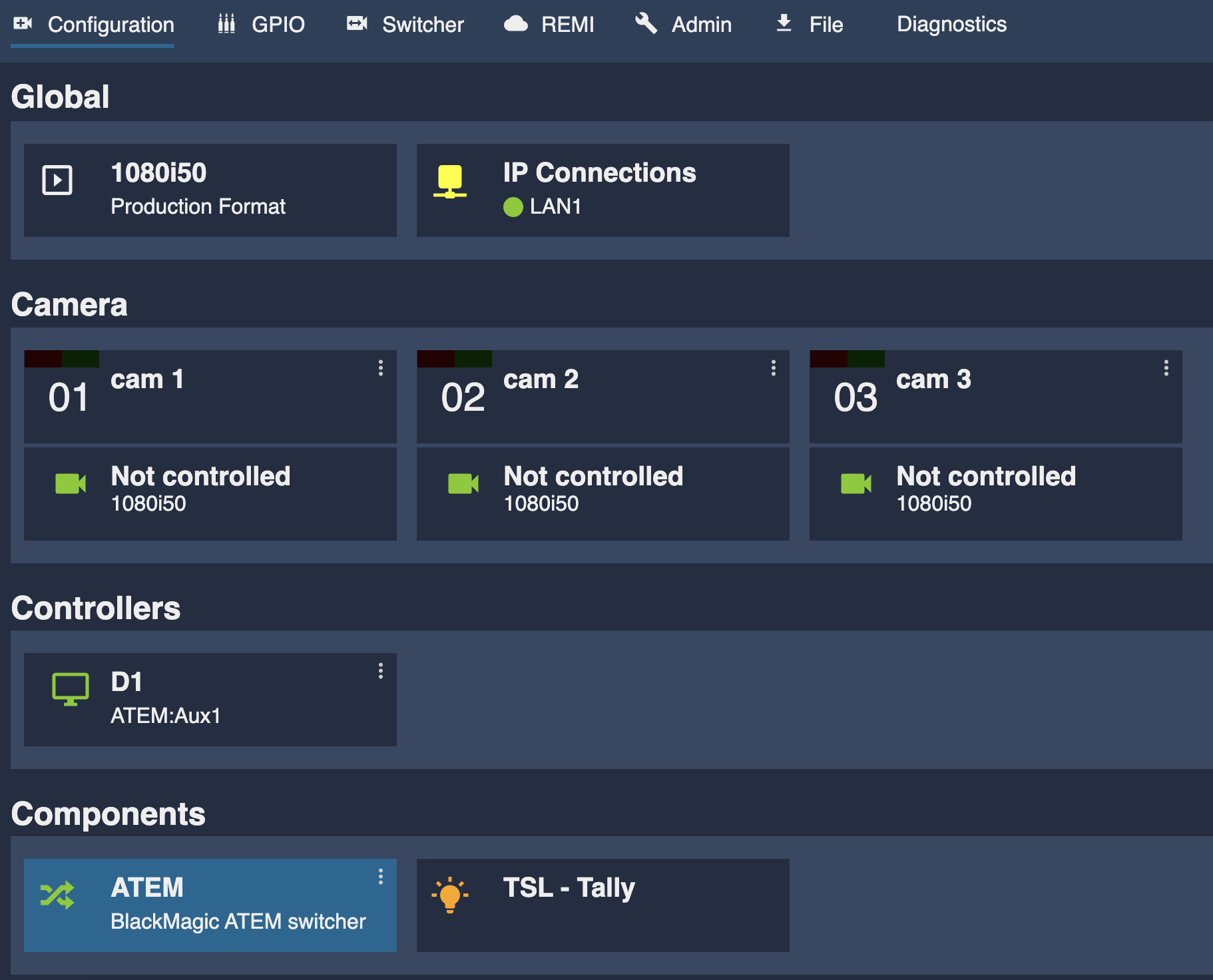
Virtual monitor
My virtual monitor D1 in the Controllers section.
I simply clicked on it, renamed RCP to D1 (and you see my RCP is already linked to it RCP-25-116 at the bottom):
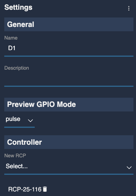
You could have multiple virtual monitors
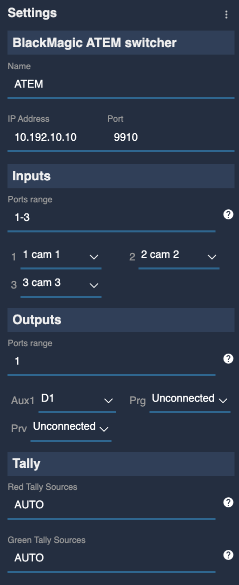
ATEM
The configuration:
- my cameras are linked to corresponding
inputs(to have proper tally and switching) - my virtual monitor (
D1) to an auxiliaryoutput(to be able to sync it with the camera on my RCP) - Configured red/green tally as AUTO (to have proper tally input)
It should look like this:
Monitor GPO
Here, I will link my virtual monitor D1:
red tallytoGPO 1green tallytoGPO 2
In the GPIO section of the web UI:
- Select in the top left corner the
GPIOselector - Find the line of your
D1virtual monitor,red_tally - Click on the
GPO 1column of your NIO (in my case,NIO-22-163) - Find the line of your
D1virtual monitor,green_tally - Click on the
GPO 2column of your NIO
It should look like this:
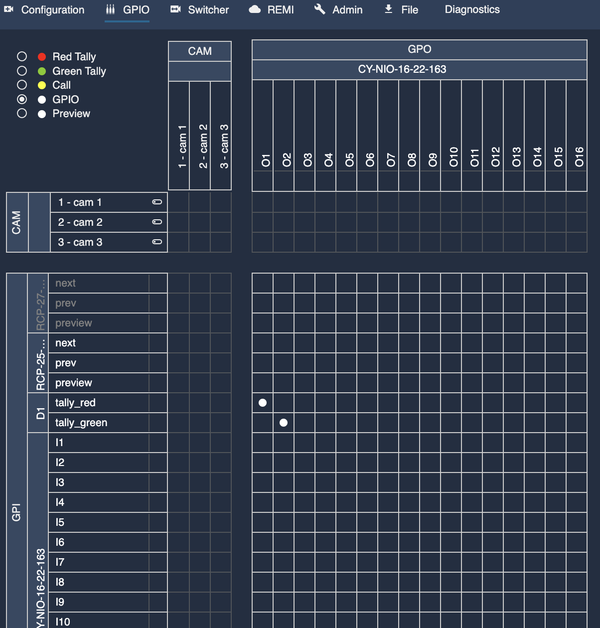
You should have white dots at the intersection of your virtual monitor tally and the corresponding GPO