VP4 Manual
Overview
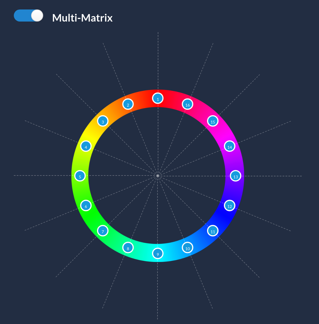
The VP4 is an advanced color corrector ideal to color match cameras. It does feature secondary corrections like a 12 vectors multimatrix and other controls only found in CCUs such as detail and coring. All channels can directly be controlled from the RCP.
Prerequisites
-
Network: the VP4 needs an ethernet connection to the RCP, and a PoE Switch is necessary to power the RCP or an external 12V power supply should be used.
-
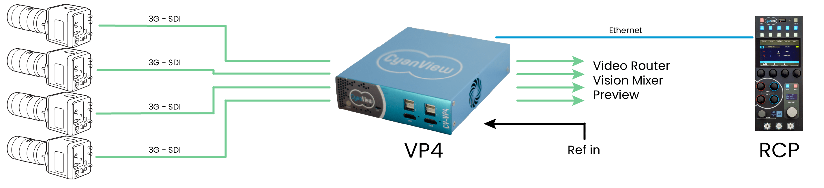
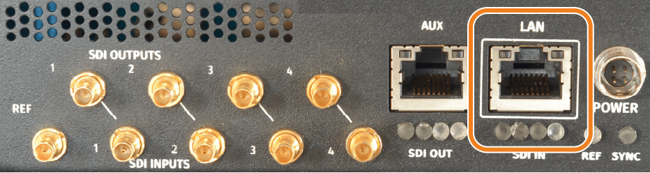
SDI Cables: 9x 3G-SDI cables with DIN 1.0/2.3 connectors are required to connect the 4 channels and reference.
-
Computer: required to access the web configuration of the RCP.
Connection
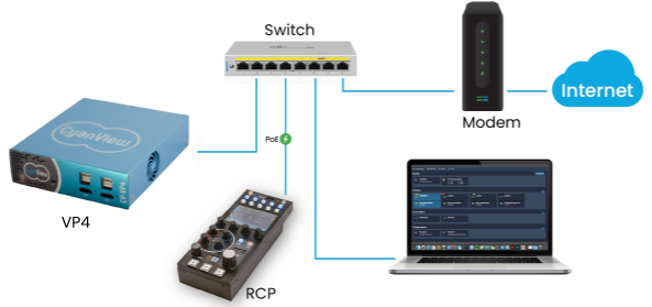
- [step 1] Network setup: connect the RCP, the VP4 LAN port and your computer to the switch. For software update, connect the switch to your internet access.
- [step 2] Video connection
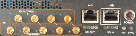
- Connectors: DIN 1.0/2.3
- Video: 720p/1080i HD-SDI or 1080p 3G-SDI in 50/59/60
- Reference: compatible with Black Burst and Tri-Level
- [step 3] Turn VP4 ON Long press on the power button will turn VP4 on/off. The boot status is displayed on the LED on the front panel.
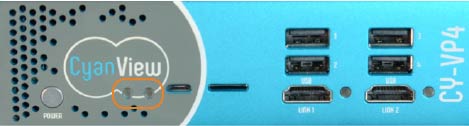
- The first LED turns green when the unit is powered.
- The second LED turns green when the unit is booted and operational.
Configuration
The VP4 can be operated in standalone using its own web UI. You can also operate it from a RCP.
VP4 channel alone
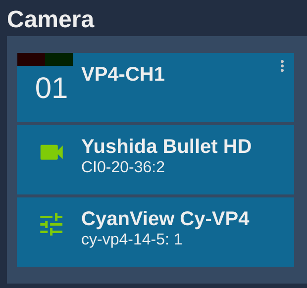
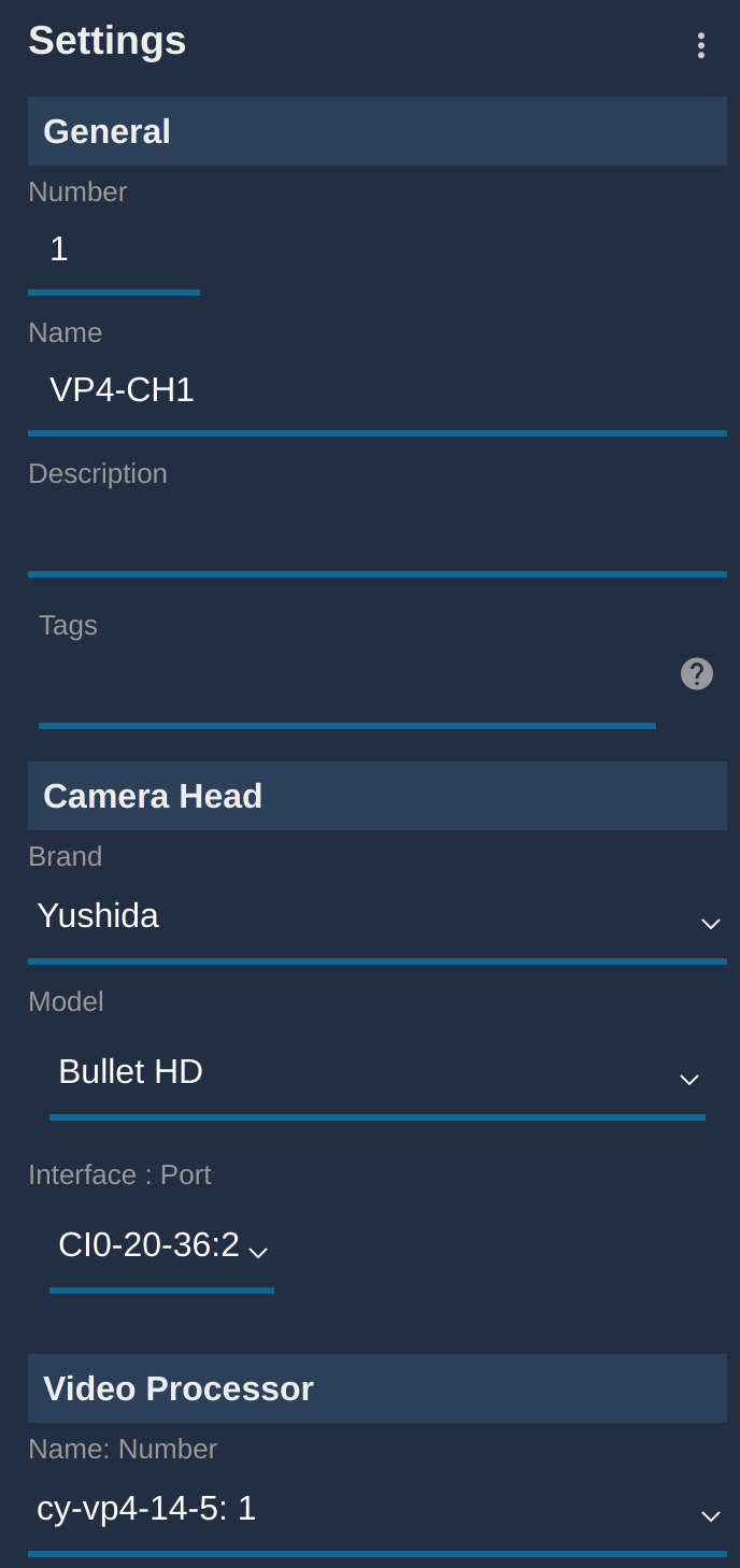
To control a VP4 channel:
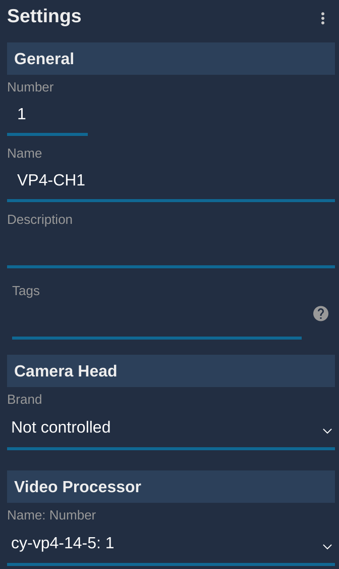
- Create a new camera, with a number and a name
- Select
Not controlledin theCamera Head - Select your VP4 and channel in the
Video processorsection - The format is:
SERIAL:CHANNEL_ID
It should look like this:
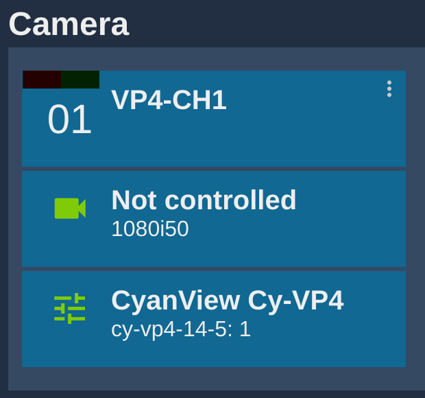
And if everything is fine, the block should appear green:
VP4 combined with camera control
To control both a camera and the VP4 combined:
- Create a new camera, with a number and a name
- Select the your camera brand and model in the list
- Select your VP4 and channel in the
Video processorsection - The format is:
SERIAL:CHANNEL_ID
It should look like this:
And if everything is fine, the block should appear green:
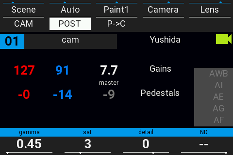
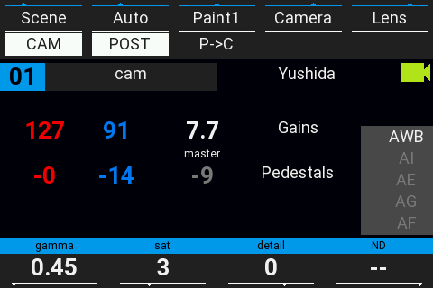
RCP operation
By default, camera head control has priority over VP4 control. For example, if both your camera and the VP4 have gain, by default, gain controls the camera gain.
In this case, 3 new buttons will appear on your RCP:
CAMto toggle the camera head controlPOSTto toggle the VP4 controlC->P|P->Cto change the camera/VP4 control priority
RCP : Camera and VP4 combined by default
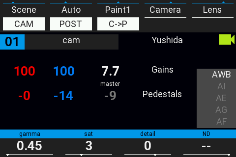
Combine camera and VP4, camera has priority (VP4 only compensate what the camera has not)
RCP : Camera only
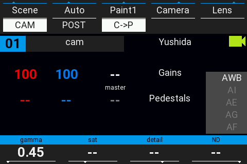
RCP : VP4 only
RCP : Camera and VP4, VP4 has priority over camera
P->Cstands for Post (processing) over Camera controlC->Pstands for Camera over Post (processing) control
Vector selection
Vectors are identified by a number from 1 to 16.
GATE will highlight the selected vector by desaturating the unselected colors. This allows a quick visual selection of the right vector. This can't be used while the camera is on air as this affect the main signal. Another option is to press the vect/peek knob which will generate a small burst of saturation on the selected vector which will be visible on the vectorscope but won't affect the live image significantly.
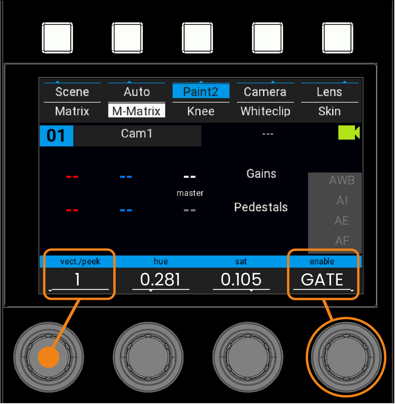
VP4 Controls
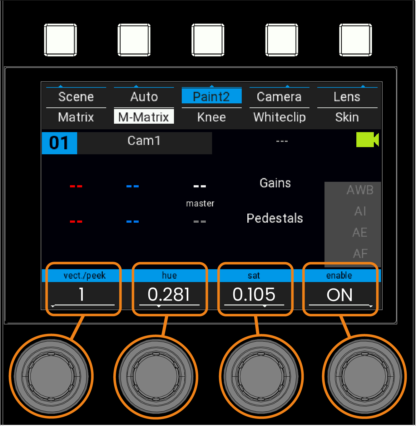
-
vect/peek Rotate the encoder to select the color vector that needs to be modified. Push the encoder will do a saturation peek allowing to identify the current color vector on screen.
-
hue Rotate to change the hue of the selected color vector.
-
Saturation Rotate the encoder to set vector color saturation.
-
enable Rotate the encoder to select OFF, ON, Gate.
- GATE will highlight the selected vector by desaturating the unselected colors.
- ON enable color correction.
- OFF disable color correction.
Genlock settings
You can configure the genlock parameters on the VP4 web interface. You can find it based on your device serial
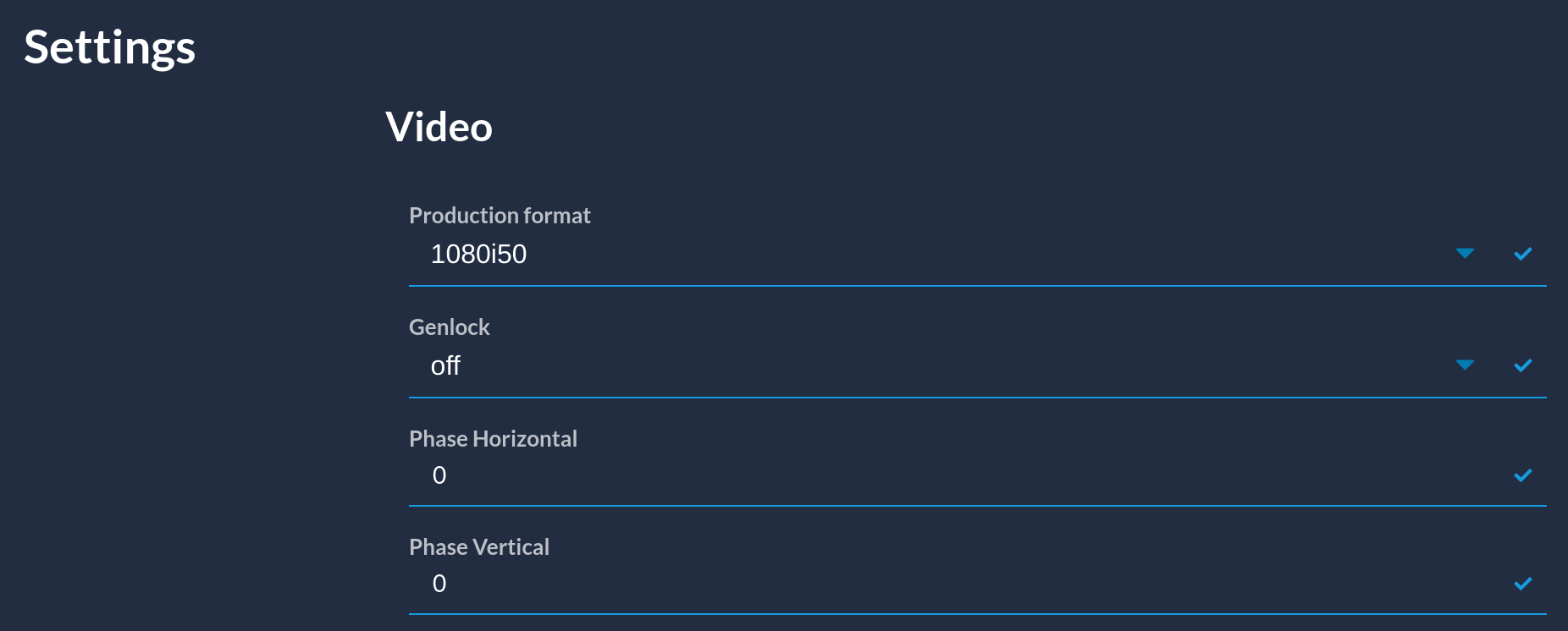
It is disabled by default (freerun) and you can:
- enable it
- change horizontal phase
- change vertical phase
Web UI operations
The VP4 color correction and color matching are operated via a Multi Matrix on the RCP.
To access the RCP Multi Matrix screen, Click on Paint1, then push the same button again to see Paint2 using the blue buttons. Then click on M-Matrix in paint2 menu using the white buttons. (see RCP Screens Overview/Navigation)
Color correction is done by selecting a color vector and the changing his hue and saturation.